Fluid Mechanics
Learning Objectives
- Define density, specific gravity, gauge pressure, and absolute pressure in fluid statics.
- Calculate hydrostatic pressure and apply Pascal's Principle.
- Understand and apply Archimedes' Principle to buoyancy problems.
- State the assumptions of ideal fluid flow.
- Apply the Equation of Continuity, Bernoulli's Equation, and Torricelli's theorem while identifying their assumptions and limitations.
- Account for pressure head, velocity head, elevation head, and specified head loss without mixing pressure references.
Fluid mechanics is the study of fluids (liquids and gases) both at rest (statics) and in motion (dynamics). It is a foundational subject for civil engineering branches like hydraulics, water resources, and environmental engineering.
Fluid Statics
Fluid Statics Concepts
Fluids differ from solids because they cannot sustain shear stress while at rest. They flow and take the shape of their container.
Density ()
Mass per unit volume. It is a fundamental property. The SI unit is .
Density Equation
Calculates density from mass and volume.
Variables
| Symbol | Description | Unit |
|---|---|---|
| Density | ||
| Mass | kg | |
| Volume |
Water Density
For water at , .
Specific Gravity (SG)
The ratio of the density of a substance to the density of a reference substance (usually water). It is a dimensionless number.
Specific Gravity Equation
Ratio of substance density to reference density.
Variables
| Symbol | Description | Unit |
|---|---|---|
| Specific Gravity | dimensionless | |
| Density of the substance | ||
| Density of water |
Pressure ()
Pressure () Concepts
Instead of dealing with forces on specific particles (which are constantly moving in a fluid), we deal with pressure.
Pressure ()
The magnitude of the normal force exerted by a fluid per unit area of a surface. It is a scalar quantity.
Pressure Equation
Calculates pressure from force and area.
Variables
| Symbol | Description | Unit |
|---|---|---|
| Pressure | Pa | |
| Normal force | N | |
| Area |
Pressure vs. Force
Pressure vs. Force: Pressure acts perpendicular to any surface it contacts. While force is a vector, pressure itself has no direction.
Hydrostatic Pressure
Hydrostatic Pressure Concepts
The pressure at any depth in a stationary liquid depends only on the depth, the density of the liquid, and gravity.
Hydrostatic Equation
Calculates absolute pressure at a given depth.
Variables
| Symbol | Description | Unit |
|---|---|---|
| Absolute pressure at depth h | Pa | |
| Pressure at the surface (often atmospheric) | Pa | |
| Density of the fluid | ||
| Acceleration due to gravity | ||
| Depth below the surface | m |
Pressure and Depth Relationship
This equation shows that pressure increases linearly with depth in an incompressible fluid (like water).
Interactive Simulation
Use this hydrostatic model to see how depth, density, and area control pressure and resultant force.
Validity gate
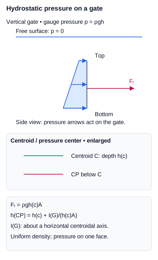
The top edge depth is 4.00 m, so the entire gate remains below the free surface. States with h_c ≤ h/2 are prevented because the fully-submerged formulas would no longer apply.
Hydrostatic Pressure Distribution and Center of Pressure
For a fully submerged vertical plane area, pressure increases linearly with depth; the resultant is based on centroid pressure and acts below the centroid.
Pascal's Principle
Pascal's Principle Concepts
If you apply pressure to an enclosed, incompressible fluid, that change in pressure is transmitted undiminished to every part of the fluid and the walls of its container.
Pascal's Principle
Pressure change in an enclosed fluid.
Variables
| Symbol | Description | Unit |
|---|---|---|
| Change in pressure | Pa |
Hydraulic Lifts
This is the principle behind hydraulic lifts. A small force applied over a small area creates a pressure . This exact same pressure appears on a larger area , producing a much larger force .
Hydraulic Lift Force Equation
Calculates the output force of a hydraulic lift given the input force and area ratio.
Variables
| Symbol | Description | Unit |
|---|---|---|
| Output force on the larger piston | N | |
| Input force on the smaller piston | N | |
| Area of the larger piston | ||
| Area of the smaller piston |
Archimedes' Principle (Buoyancy)
Archimedes' Principle (Buoyancy) Concepts
Any object, wholly or partially immersed in a fluid, is buoyed up by a force equal to the weight of the fluid displaced by the object.
Buoyant Force ()
Calculates the upward buoyant force on an object in a fluid.
Variables
| Symbol | Description | Unit |
|---|---|---|
| Buoyant force | N | |
| Density of the fluid | ||
| Submerged volume of the object | ||
| Acceleration due to gravity |
Density and Flotation
Notice that the buoyant force depends on the density of the fluid, not the object, and the volume of the object that is actually submerged ().
- If an object is denser than the fluid (), it will sink (its weight is greater than the maximum ).
- If it is less dense (), it will float. In equilibrium floating, it displaces a volume of fluid whose weight exactly equals its own total weight ().
Interactive Simulation
Use this buoyancy model to compare object weight with displaced fluid weight.
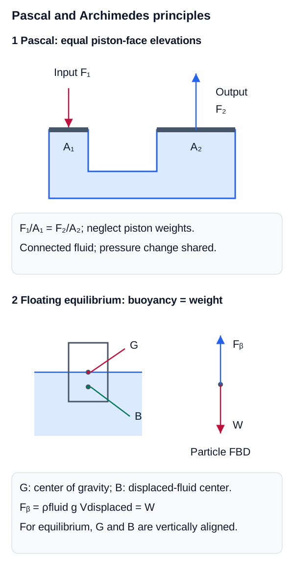
Pascal and Archimedes Force Balances
Hydraulic systems transmit pressure changes through an enclosed fluid, while buoyancy equals the weight of displaced fluid.
Fluid Dynamics
Fluid Dynamics Concepts
When fluids move, things get complicated quickly. In introductory physics and engineering, we usually start with an idealized model of fluid flow: ideal fluid flow.
Assumptions of the Introductory Ideal-Flow Model
- Steady flow: the velocity field at a fixed point does not change with time.
- Incompressible flow: density remains constant along the modeled motion.
- Inviscid flow: viscous dissipation is neglected.
- Along a streamline: the basic Bernoulli relation is applied between points on the same streamline unless stronger conditions justify a broader application.
The Equation of Continuity
The Equation of Continuity Concepts
For an incompressible fluid flowing steadily through a pipe of varying cross-sectional area, the volume flow rate () must remain constant everywhere. What goes in must come out.
Volume Flow Rate ()
The volume of fluid passing a given cross-section per unit time. The SI unit is .
Volume Flow Rate Equation
Calculates volume flow rate from area and fluid speed.
Variables
| Symbol | Description | Unit |
|---|---|---|
| Volume flow rate | ||
| Change in volume | ||
| Time interval | s | |
| Cross-sectional area | ||
| Fluid speed | m/s |
Equation of Continuity
Relates area and velocity at two points in steady flow.
Variables
| Symbol | Description | Unit |
|---|---|---|
| Cross-sectional area at point 1 | ||
| Fluid speed at point 1 | m/s | |
| Cross-sectional area at point 2 | ||
| Fluid speed at point 2 | m/s |
Flow Speed Example
This explains why a river speeds up when it passes through a narrow gorge ().
Bernoulli's Equation
Bernoulli's Equation Concepts
Bernoulli's equation is essentially a statement of the conservation of mechanical energy applied to ideal fluid flow. It relates pressure, flow speed, and elevation along a streamline.
The work done on a fluid element as it moves through a pipe changes its kinetic and potential energy.
Bernoulli's Equation
Conservation of energy principle applied to ideal fluid flow.
Variables
| Symbol | Description | Unit |
|---|---|---|
| Pressure at point 1, using a consistent absolute or gauge reference | Pa | |
| Fluid speed at point 1 | m/s | |
| Elevation at point 1 | m | |
| Pressure at point 2, using the same reference as point 1 | Pa | |
| Fluid speed at point 2 | m/s | |
| Elevation at point 2 | m | |
| Fluid density | ||
| Acceleration due to gravity | ||
| Dynamic pressure (kinetic energy per unit volume) | Pa | |
| Static pressure due to elevation (potential energy per volume) | Pa |
The Bernoulli Effect
For steady, incompressible, inviscid flow along a streamline at the same elevation, Bernoulli's equation reduces to . Within those assumptions, a section with greater speed has lower static pressure. This relation is directly useful in Venturi-type flows; by itself it is not a complete theory of aerodynamic lift.
Pressure Reference in Bernoulli Calculations
Bernoulli's equation may be written using absolute pressure or gauge pressure when the same reference is used at every point. Do not mix one absolute pressure with another gauge pressure in a single balance.
Mechanical-Energy Equation with Head Loss
Head-form energy balance for incompressible flow when irreversible losses are represented by h_L.
Variables
| Symbol | Description | Unit |
|---|---|---|
| Pressure head | m | |
| Velocity head | m | |
| Elevation head | m | |
| Head loss between sections | m |
Bernoulli Assumptions and Limitations
The basic Bernoulli equation requires the stated ideal-flow assumptions along the chosen streamline. Real pipe systems can require head-loss terms, pump/turbine work terms, and compressibility or unsteady-flow models. A correct numerical result begins by selecting the equation that matches the physical system.
Interactive Simulation
Use this pipe-flow model to connect continuity with the Bernoulli pressure-head tradeoff.
Head accounting
Q = A₁v₁ = A₂v₂.
p₁/ρg + v₁²/2g = p₂/ρg + v₂²/2g + h_L.
Both displayed pressures are gauge pressures. Adding the same atmospheric pressure to both sides would give an equivalent absolute-pressure balance.
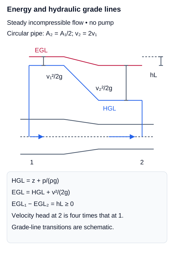
Continuity, Pressure Head, and Energy Loss
Area controls velocity through continuity; Bernoulli head accounting separates pressure head, velocity head, elevation head, and head loss.
Torricelli's Theorem
Torricelli's Theorem Concepts
A direct application of Bernoulli's equation is finding the speed of fluid exiting a small hole at the bottom of an open tank. If the hole is a distance below the surface, the surface area is much larger than the hole (), and both are at atmospheric pressure, Bernoulli's equation simplifies to Torricelli's Theorem.
Torricelli's Theorem
Fluid exit speed from an open tank.
Variables
| Symbol | Description | Unit |
|---|---|---|
| Exit velocity of fluid | m/s | |
| Acceleration due to gravity | ||
| Depth of hole below fluid surface | m |
Free Fall Analogy
This shows the fluid exits with the same speed an object would have if dropped in free fall from a height .
Variation of Pressure with Depth
The Hydrostatic Paradox
The equation implies that the pressure at a given depth in a static fluid is independent of the shape of the container or the total volume of fluid present. This leads to the "Hydrostatic Paradox":
If you have three containers of wildly different shapes (one wide, one narrow, one conical) but all filled to the exact same height with the same fluid, the pressure at the bottom of all three containers is identical. Consequently, if the bottom area is the same, the total force on the bottom of each container is exactly the same, regardless of how much total fluid is inside!
- Fluid Statics is governed by pressure increasing with depth () and Pascal's Principle (pressure applied is transmitted undiminished).
- Archimedes' Principle states that buoyancy is an upward force equal to the weight of displaced fluid ().
- Fluid Dynamics for ideal fluids relies on conservation principles.
- The Equation of Continuity () is the conservation of mass/volume flow.
- Bernoulli's Equation () is the conservation of energy, showing that pressure drops when speed increases horizontally.