Deflection of Beams
Learning Objectives
- Explain why beam deflection is a serviceability concern distinct from member strength.
- Relate bending moment to elastic-curve curvature through flexural rigidity.
- Apply double integration, moment-area, conjugate-beam, and superposition concepts appropriately.
- Select a deflection method based on the loading, desired output, and available standard solutions.
- Interpret the elastic curve without confusing exaggerated visualization with physical scale.
Elastic Curve
The elastic curve is the deflected shape of a beam's longitudinal centroidal axis while the member remains within the assumptions of elastic beam theory.
Strength versus Serviceability
A beam can remain safely below its material strength limits and still be unsatisfactory because of excessive deflection or rotation. Serviceability checks protect architectural finishes, partitions, glazing, drainage slopes, occupant comfort, and the intended appearance and function of the building.
Serviceability Interface Context
An intact floor assembly, partition, and glazing meet the same beam, showing why deformation can matter to building finishes and interfaces even when the structural member remains continuous.
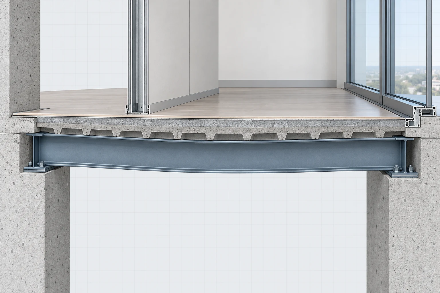
Interpreting Finish Sensitivity
Treat the floor, partition, and glazing as contextual nonstructural interfaces connected to the beam; the figure does not establish damage, tolerance, a code limit, or a measured displacement.
Elastic-Curve Differential Equation
Small-deflection relationship between bending moment and beam curvature under Euler-Bernoulli assumptions.
Flexural Rigidity
The product is the flexural rigidity. Increasing either the material modulus or the section moment of inertia reduces elastic curvature for a given bending moment. Because depends strongly on section depth, increasing depth is often far more effective than increasing width.
Deep versus Shallow Beam Context
Matching connected bays make beam depth a visible geometric cue for qualitative flexural-rigidity and sag discussion; exact EI and deflection relationships remain in the formula and simulation.
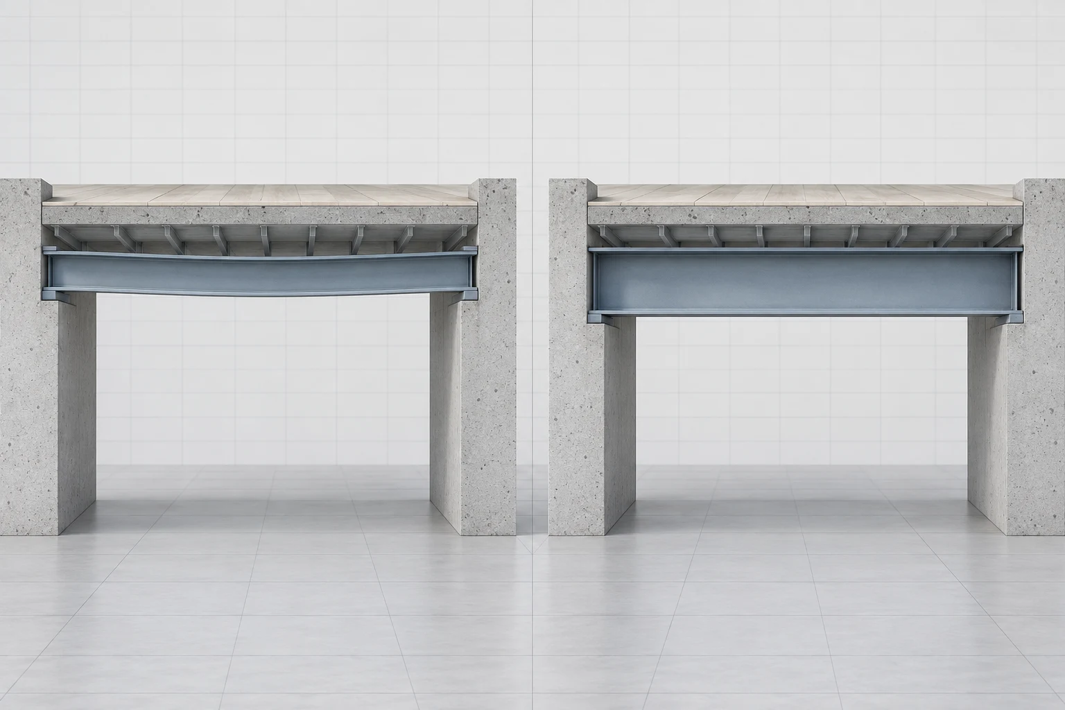
Reading the Depth Comparison
Compare the member proportions and the calm qualitative profiles, not a measured stiffness or deflection ranking. Section depth is shown as physical context for the term, while the exact relationship remains in the lesson's equation and interactive model.
Beam Deflection Context
The continuous bowing between the supports provides physical context for an elastic curve and serviceability response; use the simulation and formulas for exact curvature, slope, and deflection.
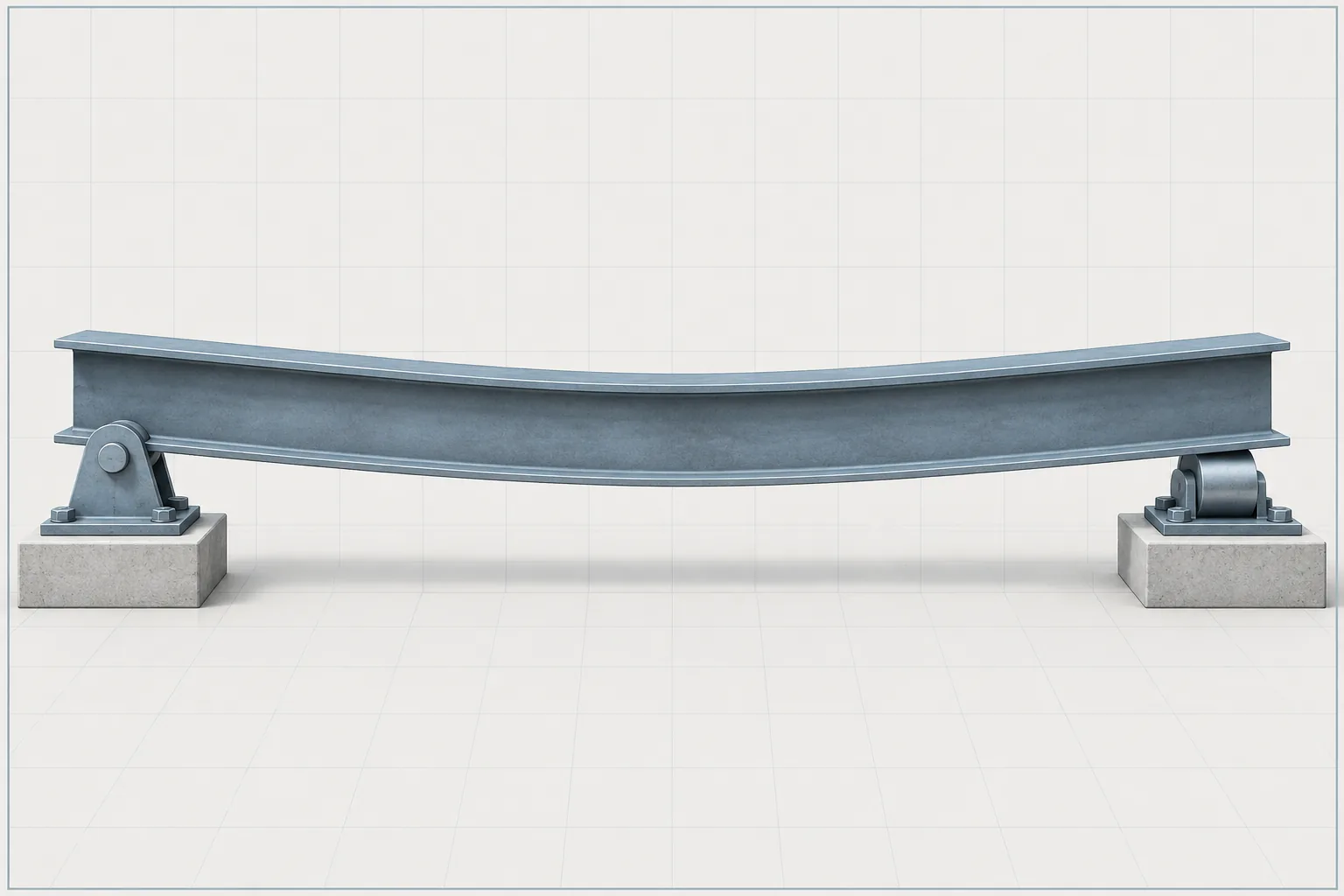
Reading the Deflected Beam
The beam and its support contacts remain intact while the shallow, continuous sag makes deformation visible. The curvature is deliberately qualitative and not to scale; it is not a measured displacement, a design limit, or a substitute for the normalized elastic curve in the simulation.
Interactive Exploration
Vary span, distributed load, modulus, and moment of inertia. Observe how the full elastic curve and maximum deflection change, and treat the plotted deformation as an instructional graph rather than a physically scaled bent beam.
Controls
5wL⁴/(384EI), downward at midspan.
Displayed as the product of the entered E and I scales.
The symmetric loading and supports require a horizontal tangent at midspan.
Double Integration Method
The double integration method obtains slope and deflection by integrating the bending-moment equation twice and evaluating constants from boundary and continuity conditions.
Cantilever Boundary Context
A continuous wall connection at one end and an unobstructed projecting end provide physical context for a cantilever boundary condition; exact slope and deflection remain in the worked methods.
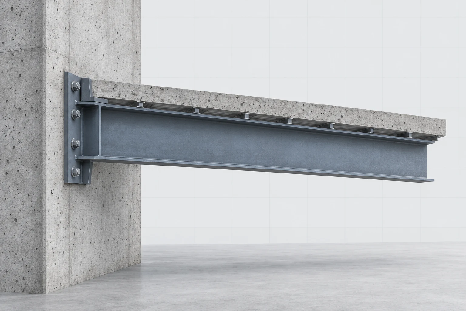
Reading the Fixed Boundary
The rigid wall connection is the defining boundary in this qualitative view, while the projecting end has no second support. Use the equations and examples for the boundary conditions, signs, and numerical response.
Slope and Deflection by Integration
Sequential integrations of the elastic-curve equation.
Moment-Area Method
The moment-area method relates changes in slope and tangential deviation to the area and first moment of the diagram.
Moment-Area Theorems
Slope change and tangential deviation obtained from the M over EI diagram.
Conjugate Beam Method
The conjugate-beam method converts an elastic-curve problem into an equivalent statics problem. The real beam's diagram becomes the loading on the conjugate beam; conjugate-beam shear corresponds to real-beam slope, and conjugate-beam moment corresponds to real-beam deflection. Correct support transformation is essential.
Superposition
For a linear-elastic system with small deflections, the response from several load cases is the algebraic sum of the responses produced by each load separately. This makes verified beam-formula tables highly efficient for standard loading patterns.
Beam Superposition Load-Case Context
A single beam shares one architectural assembly with several independent service contexts, illustrating why separate load cases can contribute to one overall response; the raster contains no load values or response sum.
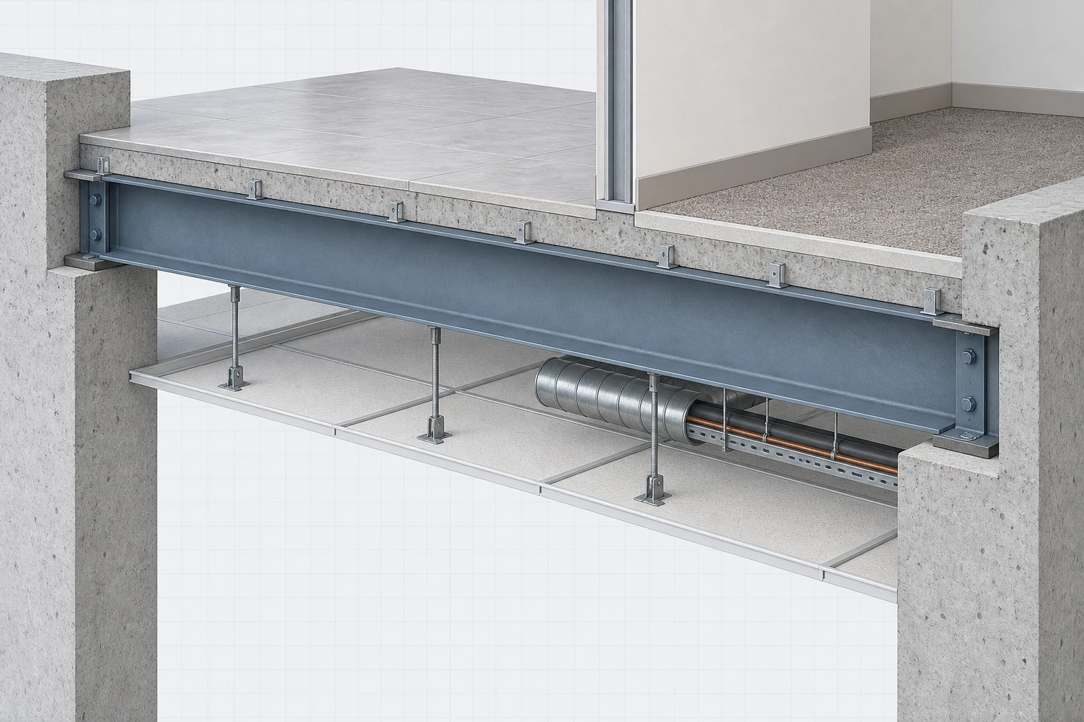
Interpreting Multiple Service Conditions
Read the floor, partition, ceiling, and service-support elements as distinct qualitative contexts on one connected beam. The algebraic combination and the linearity limits are defined by the adjacent concept and caution, not by the raster.
Superposition Limits
Do not use linear superposition after substantial yielding, large geometric change, support-condition change, or another nonlinearity that causes one load case to alter the structural response to another.
Method Selection Workflow
Choose a deflection method based on what must be found and how the loading is represented. The workflow below is a guide, not a replacement for engineering judgment.
Define beam, EI, loading, and required response → Can the loading be decomposed into verified standard cases?; Can the loading be decomposed into verified standard cases? — Yes → Use superposition and beam-formula solutions; Can the loading be decomposed into verified standard cases? — No → Is a continuous slope/deflection equation required?; Use superposition and beam-formula solutions → Apply boundary, sign, unit, and symmetry checks; Is a continuous slope/deflection equation required? — Yes → Use double integration or singularity functions; Is a continuous slope/deflection equation required? — No → Is slope/deflection needed mainly at selected points?; Use double integration or singularity functions → Apply boundary, sign, unit, and symmetry checks; Is slope/deflection needed mainly at selected points? — Yes → Use moment-area where M/EI geometry is convenient; Is slope/deflection needed mainly at selected points? — No / alternate → Use conjugate beam when a statics transformation is advantageous; Use moment-area where M/EI geometry is convenient → Apply boundary, sign, unit, and symmetry checks; Use conjugate beam when a statics transformation is advantageous → Apply boundary, sign, unit, and symmetry checks; Apply boundary, sign, unit, and symmetry checks → Report slope/deflection and assumptions
- Define beam, EI, loading, and required response: terminator
- Can the loading be decomposed into verified standard cases?: decision
- Use superposition and beam-formula solutions: process
- Is a continuous slope/deflection equation required?: decision
- Use double integration or singularity functions: process
- Is slope/deflection needed mainly at selected points?: decision
- Use moment-area where M/EI geometry is convenient: process
- Use conjugate beam when a statics transformation is advantageous: process
- Apply boundary, sign, unit, and symmetry checks: process
- Report slope/deflection and assumptions: terminator
- Beam deflection is primarily a serviceability response and must be checked separately from strength.
- Flexural rigidity controls elastic curvature and deflection.
- Double integration gives a continuous response; moment-area and conjugate-beam methods can simplify selected-point calculations.
- Superposition is efficient only when linearity and small-deflection assumptions remain valid.
- Every method should satisfy support conditions, sign conventions, dimensions, and symmetry or limiting-case checks.