Kinematics
Learning Objectives
- Define and calculate displacement, velocity, and acceleration with civil engineering context.
- Understand the difference between average and instantaneous kinematic quantities.
- Derive and apply the kinematic equations for 1D motion with constant acceleration.
- Analyze 2D projectile motion by separating it into independent horizontal and vertical components.
- Calculate tangential and centripetal acceleration in circular motion for transportation design.
- Solve relative motion problems in 1D and 2D using vector addition.
Key Kinematic Quantities
Key Kinematic Quantities Concepts
To describe motion, we use a specific set of parameters. All of these (except time and distance) are vector quantities.
Displacement ()
The change in position of an object. It is a vector pointing from the initial position to the final position.
Note: Displacement is not the same as the total distance traveled, which is a scalar representing the actual path length.
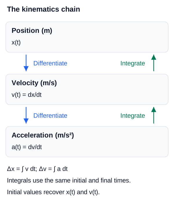
Kinematics relationship map
The kinematics chain
Differentiation moves from position to velocity to acceleration; integration reverses the chain and accumulates signed changes.
Average vs Instantaneous
Average vs Instantaneous Concepts
In kinematics, it is critical to distinguish between average values over a time interval and instantaneous values at a specific moment.
Average Velocity ()
The total displacement divided by the time interval during which the displacement occurred. It points in the same direction as the displacement.
Contrast this with average speed, which is total distance divided by total time (a scalar).
Instantaneous Velocity ()
The velocity of an object at a specific instant in time. Mathematically, it is the limit of the average velocity as the time interval approaches zero. It is the derivative of position with respect to time.
Acceleration ()
The rate of change of velocity with respect to time. An object is accelerating if its speed changes, its direction changes, or both.
Graphical Analysis of Motion
Position-Time Graph (x vs t)
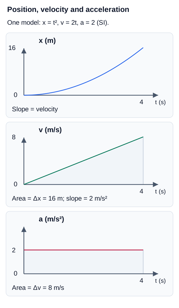
A graph where the slope of the tangent line at any point represents the instantaneous velocity. A constant slope indicates constant velocity. A curve indicates changing velocity (acceleration).
Velocity-Time Graph (v vs t)
A graph where the slope of the tangent line represents instantaneous acceleration. The area under the curve between two times represents the displacement.
Acceleration-Time Graph (a vs t)
A graph where the area under the curve represents the change in velocity.
Graphical Analysis of Motion Concepts
Graphs are powerful tools for visualizing kinematics. The slope and area under curves provide vital information regarding position, velocity, and acceleration over time.
Motion-graph interpretation
Motion graph relationships
Slope of x-t gives velocity, slope of v-t gives acceleration, area under v-t gives displacement, and area under a-t gives velocity change.
Deriving the Kinematic Equations (Calculus Approach)
Deriving the Kinematic Equations (Calculus Approach) Concepts
For engineering mechanics, it is essential to understand that kinematic equations are derived using fundamental calculus operations on the definitions of velocity and acceleration.
Given , we can integrate with respect to time to find velocity. If acceleration is constant:
Velocity from Constant Acceleration
Integrates constant acceleration over time to find the velocity equation.
Variables
| Symbol | Description | Unit |
|---|---|---|
| Final velocity | m/s | |
| Initial velocity | m/s | |
| Constant acceleration | ||
| Time interval | s |
Deriving Position from Velocity
Given , we substitute the velocity equation and integrate again to find position:
Position from Constant Acceleration
Integrates velocity over time to find the position equation under constant acceleration.
Variables
| Symbol | Description | Unit |
|---|---|---|
| Final position | m | |
| Initial position | m | |
| Initial velocity | m/s | |
| Constant acceleration | ||
| Time interval | s |
Time-Independent Derivation
If we need a relationship independent of time, we use the chain rule: . Separating variables and integrating yields .
1D Motion with Constant Acceleration
1D Motion with Constant Acceleration Concepts
When an object's acceleration is constant (like a car braking uniformly, or an object in free fall near Earth's surface), its motion can be completely described by four foundational equations, often called the "Big Four" kinematic equations. As shown above, these are derived directly from calculus.
Kinematic Equation 1: Velocity as a Function of Time
Calculates final velocity given initial velocity, constant acceleration, and time.
Variables
| Symbol | Description | Unit |
|---|---|---|
| Final velocity | m/s | |
| Initial velocity | m/s | |
| Constant acceleration | ||
| Time interval | s |
Kinematic Equation 2: Displacement as a Function of Time
Calculates displacement given initial velocity, time, and constant acceleration.
Variables
| Symbol | Description | Unit |
|---|---|---|
| Displacement | m | |
| Initial velocity | m/s | |
| Constant acceleration | ||
| Time interval | s |
Kinematic Equation 3: Velocity as a Function of Displacement
Calculates final velocity without knowing the time interval.
Variables
| Symbol | Description | Unit |
|---|---|---|
| Final velocity | m/s | |
| Initial velocity | m/s | |
| Constant acceleration | ||
| Displacement | m |
Kinematic Equation 4: Displacement using Average Velocity
Calculates displacement using initial and final velocity without knowing acceleration.
Variables
| Symbol | Description | Unit |
|---|---|---|
| Displacement | m | |
| Initial velocity | m/s | |
| Final velocity | m/s | |
| Time interval | s |
Interactive Simulation
Use the graph simulator to see how changing initial velocity, acceleration, and time reshapes the position-time and velocity-time curves.
Free Fall
Free Fall Concepts
A classic example of constant 1D acceleration is an object falling under the sole influence of gravity near the Earth's surface. In this case, the acceleration is constant and directed downwards: (assuming the positive y-axis points upward).
Note: In true free fall, the mass, size, and shape of the object do not affect its acceleration (neglecting air resistance).
2D Motion: Projectile Motion
2D Motion: Projectile Motion Concepts
When an object is launched into the air and moves in two dimensions under the influence of gravity alone, it is in projectile motion. A key assumption is that air resistance is negligible.
The fundamental principle for solving projectile motion problems is the independence of motion: the horizontal () and vertical () motions are completely independent of each other, except that they share the same elapsed time ().
Projectile Motion Principles
Horizontal Motion (x-axis):
Because gravity acts purely vertically, there is no horizontal acceleration.
- Acceleration is zero ().
- Velocity is constant ().
- Equation:
Vertical Motion (y-axis):
The vertical motion is identical to 1D free fall.
- Acceleration is constant gravity ().
- Velocity changes continuously.
- Equations: The standard 1D kinematic equations apply, substituting for and for .
Initial Velocity Components
If a projectile is launched from the origin with an initial velocity at an angle above the horizontal, we must resolve the initial velocity into components:
Initial Horizontal Velocity
The initial horizontal component of the projectile's velocity.
Variables
| Symbol | Description | Unit |
|---|---|---|
| Initial horizontal velocity | m/s | |
| Initial launch speed | m/s | |
| Launch angle relative to horizontal | deg/rad |
Initial Vertical Velocity
The initial vertical component of the projectile's velocity.
Variables
| Symbol | Description | Unit |
|---|---|---|
| Initial vertical velocity | m/s | |
| Initial launch speed | m/s | |
| Launch angle relative to horizontal | deg/rad |
Interactive Simulation
Adjust launch conditions below to connect horizontal constant velocity with vertical free-fall acceleration.
Key Projectile Characteristics
Maximum Height
Occurs when the vertical velocity .
Time of Flight
The total time the projectile is in the air. For a launch and landing at the same elevation, it is twice the time to reach maximum height.
Range ()
The horizontal distance covered. For a launch and landing at the same elevation, . Maximum range is achieved at .
Key Projectile Characteristics Concepts
Understanding key projectile characteristics such as maximum height, time of flight, and range is crucial for analyzing 2D motion under gravity.
Circular Motion Acceleration
Circular Motion Acceleration Concepts
When an object moves along a curved path, its acceleration can be broken into two orthogonal components: tangential and normal (centripetal) acceleration.
Tangential Acceleration
The component of acceleration parallel to the velocity vector, changing the speed.
Variables
| Symbol | Description | Unit |
|---|---|---|
| Tangential acceleration | ||
| Magnitude of velocity (speed) | m/s | |
| Time | s |
Centripetal (Normal) Acceleration
The component of acceleration perpendicular to velocity, changing the direction towards the center of curvature.
Variables
| Symbol | Description | Unit |
|---|---|---|
| Centripetal acceleration | ||
| Magnitude of velocity (speed) | m/s | |
| Radius of curvature | m |
Uniform Circular Motion
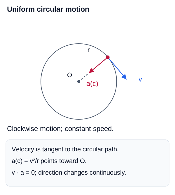
In uniform circular motion (constant speed), , and the object only experiences centripetal acceleration. In transportation engineering, understanding this centripetal acceleration is critical when designing horizontal curves for highways and railways to ensure vehicles don't slip outward due to insufficient friction or banking.
Circular-motion kinematics visual
Velocity and acceleration in circular motion
Velocity is tangent to the path while centripetal acceleration points toward the instantaneous center of curvature.
Relative Motion
Relative Motion Concepts
Velocity is not absolute; it depends on the frame of reference of the observer. If you are sitting in a train moving at 50 m/s relative to the ground, your velocity relative to the train is zero, but your velocity relative to an observer on the platform is 50 m/s.
If object A is moving with velocity relative to Earth, and object B is moving with velocity relative to Earth, the velocity of object A relative to object B () is:
1D Relative Velocity
Velocity of object A relative to object B.
Variables
| Symbol | Description | Unit |
|---|---|---|
| Velocity of A relative to B | m/s | |
| Velocity of A relative to Earth | m/s | |
| Velocity of B relative to Earth | m/s |
Relative Motion Addition
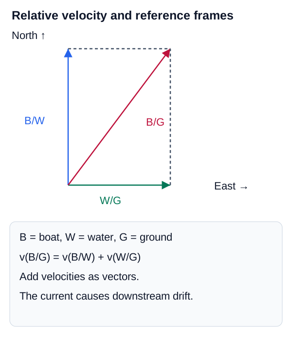
Alternatively, the velocity of an object relative to a stationary frame () is the sum of the velocity of the object relative to a moving frame () and the velocity of the moving frame relative to the stationary frame ():
Relative Velocity Addition
Finding absolute velocity from relative velocity and moving frame velocity.
Variables
| Symbol | Description | Unit |
|---|---|---|
| Velocity of P relative to Earth | m/s | |
| Velocity of P relative to moving frame M | m/s | |
| Velocity of moving frame M relative to Earth | m/s |
Relative Velocity in 2D
Moving Reference Frames
While relative motion in 1D is simply vector addition or subtraction along a line, relative velocity in 2D requires vector algebra. This is essential for analyzing the motion of airplanes in crosswinds or boats crossing rivers with currents.
If is the velocity of object P relative to frame A, and is the velocity of frame A relative to frame B, then the velocity of object P relative to frame B is the vector sum:
2D Relative Velocity
Vector addition of relative velocities across different reference frames.
Variables
| Symbol | Description | Unit |
|---|---|---|
| Velocity of P relative to B | m/s | |
| Velocity of P relative to A | m/s | |
| Velocity of A relative to B | m/s |
Applications
To solve these problems, engineers decompose the velocity vectors into their and components and solve them independently using the standard component method discussed in the previous section.
Relative-motion vector visual
Relative velocity vector addition
A moving object's absolute velocity equals its velocity relative to a moving frame plus the frame velocity relative to the reference frame.
- Kinematics describes motion without forces. Key quantities are position, displacement, velocity, and acceleration.
- Distinguish between average (interval) and instantaneous (point in time) quantities. Derivatives and integrals link position, velocity, and acceleration.
- The Kinematic Equations apply only when acceleration is constant.
- For Free Fall, acceleration is constant (). Mass is irrelevant.
- Projectile Motion is analyzed by separating it into independent, constant-velocity horizontal motion and constant-acceleration vertical motion, linked only by time.
- Relative velocity requires defining a reference frame and using vector addition/subtraction.