Explain how civil engineers communicate through drawings, calculations, reports, specifications, schedules, models, meetings, and field records.
Interpret common drawing views and sheet types used in civil and structural work, including plans, profiles, elevations, sections, cross-sections, and details.
Recognize standard drawing conventions such as scales, grids, datums, dimensions, symbols, notes, callouts, legends, revisions, and title blocks.
Explain the roles of RFIs, submittals, shop-drawing reviews, site instructions, non-conformance reports, change documentation, inspections, and meeting records.
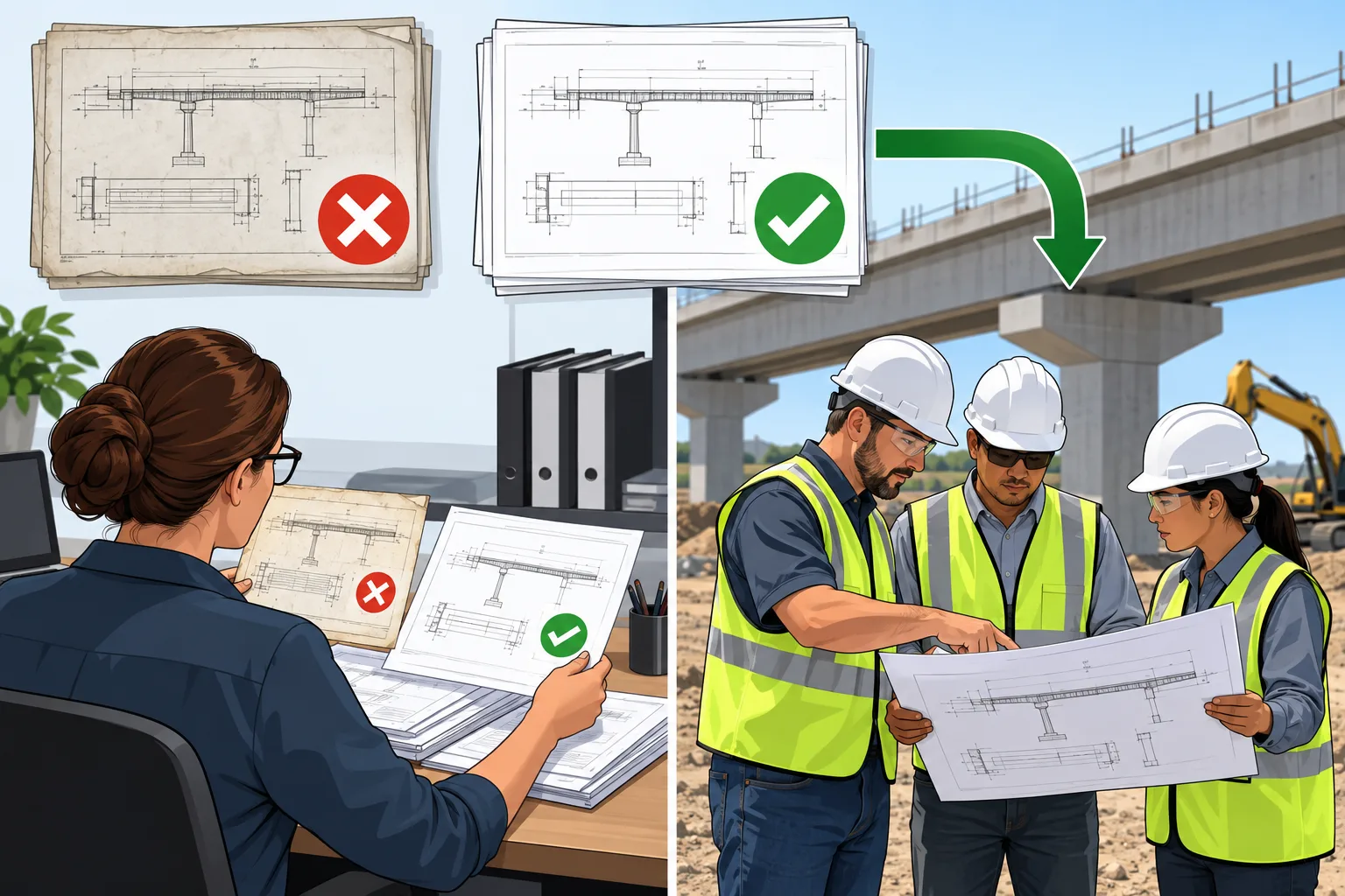
Apply document-control principles so teams can identify the current approved information and avoid building from superseded revisions.
Explain why technical communication, checking, approval, signing/sealing, and revision traceability are matters of professional responsibility.
Civil engineering is collaborative. A technically sound design can still fail in practice if assumptions, dimensions, revisions, interfaces, or instructions are communicated poorly. Engineering communication therefore aims to make information clear, traceable, reviewable, coordinated, and appropriate for the person who must act on it.
Forms of Engineering Communication
Technical writing
Civil engineers may prepare:
feasibility studies;
geotechnical and site-investigation reports;
structural or hydraulic calculation reports;
design-basis reports;
technical memoranda;
method statements;
inspection and site reports;
progress reports;
material or testing reports;
specifications;
executive summaries and stakeholder presentations.
Good technical writing states the purpose, inputs, assumptions, methods, evidence, results, limitations, and required action.
Geotechnical reports provide recommendations, not magic numbers
A geotechnical report typically presents investigation data, ground interpretation, engineering parameters, groundwater information, hazards, and recommendations for foundations, excavations, slopes, or earthworks.
A value such as allowable bearing pressure must be interpreted in context: foundation size/depth, settlement criteria, groundwater, variability, loading, and project-specific recommendations can all matter. The report informs the designer; it does not replace engineering judgment.
Calculation reports
A calculation report should allow a competent reviewer to understand and reproduce the engineering reasoning. Useful content can include:
design criteria and governing references;
geometry and material assumptions;
loads and combinations;
analytical model assumptions;
representative hand checks;
critical results and governing cases;
design checks;
limitations and outstanding items;
software/version information where relevant.
A calculation report can be short or extensive depending on the project; page count is not a measure of engineering quality.
Project specifications
Specifications define project-specific requirements for materials, workmanship, testing, execution, tolerances, quality, submittals, and acceptance.
Drawings and specifications should be read together. Do not teach that specifications are automatically "more legally binding" than drawings in every project; the governing contract establishes the order of precedence and method for resolving conflicts.
Clarity, precision, and appropriate context
Engineering communication should minimize ambiguity, but "clear" does not mean oversimplified. A document should state enough context that the reader can distinguish requirements, assumptions, recommendations, alternatives, uncertainties, and unresolved issues.
Engineering Drawings as a Coordinated Information Set
Computer-Aided Design (CAD)
The use of software to create, edit, coordinate, and document engineering geometry and drawings. CAD dominates professional production, but hand sketches remain valuable for conceptual thinking, field clarification, review, and communication.
A drawing set is not simply a collection of pictures. Sheets reference one another through grids, sections, details, notes, schedules, coordinates, and revisions. The reader must learn how to navigate the set as a connected system.
Primary Views
Plan View
A plan is a horizontal view or horizontal cut used to show layout and location.
Examples include:
site-development plan;
foundation plan;
framing plan;
grading plan;
drainage plan;
utility plan;
road alignment plan.
The exact cut plane and information shown depend on the discipline and drawing type.
Elevation View
An elevation shows a vertical face or projected side of an object or structure. It can communicate heights, levels, exterior geometry, member positions, slopes, openings, and finishes or civil features depending on the drawing.
Section View
A section cuts through the object or site to reveal internal or vertical relationships that cannot be understood from plan alone.
Examples:
building/structural sections;
retaining-wall sections;
drainage-channel sections;
foundation sections;
bridge deck/girder sections.
Profile and Longitudinal Section
Civil works frequently use a profile along an alignment to show existing ground, proposed grade, stations, elevations, vertical curves, pipe invert levels, utilities, or longitudinal hydraulic information.
Cross-Section
A cross-section is taken perpendicular to an alignment and is common in roads, railways, channels, earthworks, and pipelines. It can show pavement layers, side slopes, cut/fill, drainage, right-of-way, and terrain.
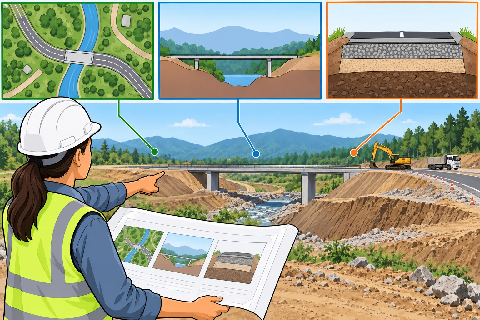
Communicate the Same Work in Multiple Views
Plan, profile, and section views answer different spatial questions; coordinate them with field evidence instead of treating any one view as the whole design.
Detail View
A detail enlarges a specific connection, reinforcement arrangement, joint, drainage feature, anchor, pavement layer, or other location that requires more information than the general drawing can show.
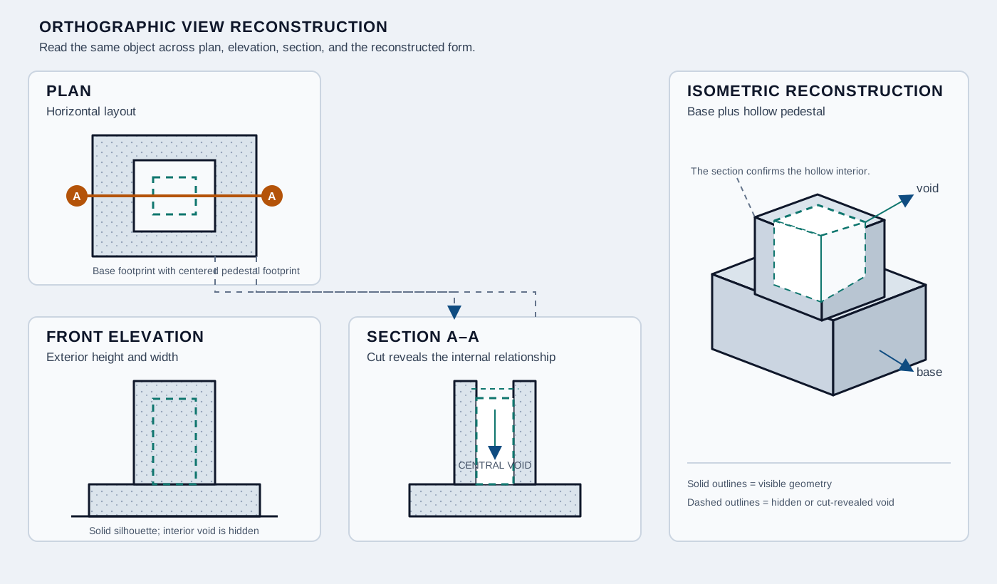
Orthographic View Reconstruction
Read the same fixed geometry across plan, elevation, section, and isometric views; visible and hidden lines must agree across the set.
Interactive blueprint viewer
Use the viewer below to connect a simple 3D object with its plan, elevation, and section. In professional work, extend the same spatial reasoning to profiles, cross-sections, details, reinforcement drawings, and coordinated multidisciplinary sheets.
Interactive learning lab · 3 experiences
Engineering Communication and Plans Learning Lab
Explore a coordinated civil/structural drawing set, practice document-control decisions, and resolve interdisciplinary conflicts using traceable project communication instead of assumptions or undocumented field changes.
Drawing Set Explorer
Follow the same infrastructure elements through different drawings and understand why plan, profile, section, detail, schedules, notes, and specifications must be read together.
What to observe
No single drawing tells the entire project story. A competent reader traces references, grids, datums, dimensions, callouts, details, revisions, notes, and related specifications before acting.
Site / civil plan
Horizontal organization of the project
A site or civil plan can show property/context information, roads, grading, drainage, utilities, structures, coordinates, setbacks, contours, spot levels, north orientation, and references to other sheets.
North arrow and coordinate/grid references
Existing vs proposed information
Grading and drainage relationships
Utility and access coordination
Drawing Conventions You Must Learn to Read
Common drawing elements
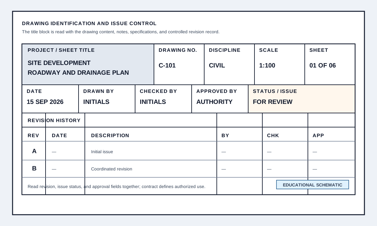
Title block: project, sheet title/number, discipline, issue status, dates, approvals, and organization information.
Scale: relationship between drawing distance and real distance; some details may use a different scale from the sheet.
North arrow / orientation: establishes direction where applicable.
Grid lines: reference framework for locating columns, walls, structural elements, or building zones.
Datums and benchmarks: reference elevations or coordinate control.
Dimensions: explicit geometric requirements; avoid scaling a drawing when a governing dimension is provided.
Line types and line weights: distinguish visible, hidden, center, cut, projection, boundary, and other information.
Legends and symbols: explain discipline-specific notation.
Section and detail callouts: point to another view or sheet containing the required information.
General and specific notes: communicate requirements not practical to draw graphically.
Schedules: tabulate repetitive information such as reinforcement, columns, beams, doors, pipes, or finishes.
Revision clouds and revision blocks: identify changed information and its issue history.
Title Block and Issue Control
Confirm sheet identity, discipline, issue status, revision history, and approval information before relying on a drawing in design or construction.
Never assume the graphic scale is authoritative after copying or resizing
PDFs, screenshots, prints, and exported images can be resized. Use stated dimensions, coordinates, levels, and the controlled drawing scale rather than measuring an uncontrolled image unless the document explicitly permits scaling.
Typical Civil / Structural Drawing Sets
Examples of sheet groups
A project may contain:
cover sheet, drawing index, legends, and general notes;
survey / existing-conditions information;
site-development and grading plans;
road, drainage, utilities, or earthworks plans/profiles;
structural foundation and framing plans;
elevations and sections;
reinforcement and connection details;
schedules and standard details;
temporary-works or construction-stage information where applicable;
record/as-built information after construction.
The exact organization depends on the project and discipline.
Design, Construction, Shop, and Record Information
Detailed design / construction documents: communicate the coordinated requirements intended for procurement and construction, subject to project approval status.
Tender / bid documents: define information issued for pricing and procurement.
Shop drawings: contractor/supplier-produced information showing how specific work will be fabricated, assembled, coordinated, or installed. Review does not automatically transfer the contractor's means/methods responsibility to the designer.
Fabrication drawings: detailed manufacturing information for components.
Record / as-built information: documents the final installed condition to the level required by the contract and project procedures.
Issue status matters
A technically correct drawing marked For Review, For Information, or Superseded may not be authorized for construction. Teams must understand the project's document-status system before acting on a drawing.
Interdisciplinary Coordination
Civil projects are interface problems
A single project may require coordination among:
civil/site;
structural;
geotechnical;
architecture;
mechanical;
electrical;
plumbing;
fire protection;
surveying/geodetic;
environmental;
contractors, suppliers, and operators.
Examples of coordination failures include a drainage pipe passing through a footing, a beam conflicting with ductwork, a road profile conflicting with utility cover, or structural openings missing from the design model.
Coordination is more than clash detection
Geometric clashes are only one category. Teams must also coordinate:
loads and support reactions;
levels and datums;
design criteria;
clearances and access;
maintenance zones;
fire/life-safety requirements;
material interfaces;
construction sequence;
temporary works;
revision timing;
responsibilities and approval boundaries.
Field and Contract Communication
Construction produces questions and changes because real conditions, procurement, sequencing, and coordination can differ from early assumptions. Formal communication creates traceability and ensures the right party evaluates the issue.
Request for Information (RFI)
An RFI is commonly used to request clarification of an ambiguity, conflict, missing information, or unforeseen condition. It should describe the issue clearly, reference the affected drawing/specification/location, and avoid hiding a proposed change inside a vague question.
Submittals and shop drawings
Contractors and suppliers may submit product data, samples, mix designs, shop drawings, calculations, method information, and other required evidence for review according to the contract.
Review status and responsibility depend on the contract. A review stamp should never be interpreted as unlimited acceptance of every dimension, means/method, or unreviewed deviation.
Site instruction / supplemental instruction
Designers or contract administrators may issue clarifications or instructions using terminology defined by the contract or organization. Terms such as ASI are common in some systems but are not universal across all civil projects.
Change / variation documentation
When scope, price, time, or contract requirements change, the project needs the appropriate formal change process. The exact document may be called a change order, variation order, contract amendment, site instruction with valuation, or another term depending on the contract.
Non-Conformance Report (NCR)
An NCR documents work, material, or a process that does not conform to a specified requirement. Resolution may involve repair, replacement, rework, engineering evaluation, concession where contractually permitted, or another controlled disposition.
Inspection and test records
Inspection requests, checklists, test reports, punch lists, photographs, survey records, and acceptance documents create evidence of what was checked and what remains unresolved.
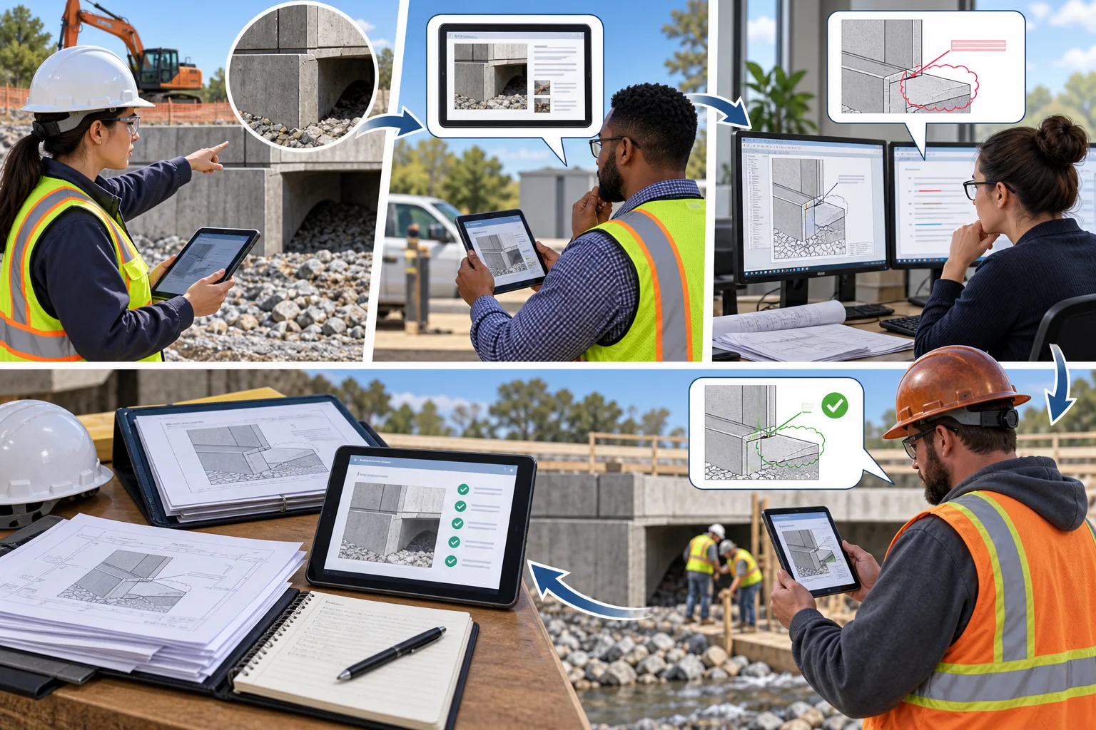
RFI and Submittal Coordination
A formal question and response should identify the affected work, controlled references, responsible reviewers, decision, and resulting action.
Meeting minutes and daily records
Meeting minutes, daily reports, progress records, weather/site logs, manpower/equipment records, and action lists help reconstruct decisions and project history. They should distinguish facts, decisions, responsibilities, and deadlines.
Document Control and Revision Management
The right information must reach the right person at the right revision
Many construction errors are not caused by a lack of engineering knowledge but by building from an old drawing, missing a revision, using an unapproved submittal, or acting on a change that was never distributed correctly.
Basic document-control questions
What is the document number and revision?
What is its current status: draft, review, approved, construction, superseded, record, or another controlled status?
Who prepared, checked, reviewed, and approved it?
When was it issued and to whom?
What changed from the previous revision?
Are referenced sheets/details/specifications at compatible revisions?
Has the site team acknowledged the new issue?
Has superseded information been removed or clearly marked?
Is the decision/action traceable to an RFI, instruction, submittal, meeting, or change record?
Common Data Environment (CDE)
Digital projects may use a CDE or document-management platform to control file naming, metadata, status, permissions, reviews, transmittals, and revisions. The software helps, but the team still needs clear information-management rules and disciplined behavior.
Revision-Controlled Document Set
Keep superseded and current information distinguishable, and ensure the people acting on the work receive the approved current revision.
Controlled Engineering Communication Workflow
Move a technical change or question through revision control, clarity checks, review, distribution, acknowledgment, and a traceable record.
Identify a technical question, change, or instruction → Locate the current controlled documents and affected revisions; Locate the current controlled documents and affected revisions → Is the required action clear, coordinated, and supported by evidence?; Is the required action clear, coordinated, and supported by evidence? — No → Prepare an RFI, submittal comment, change record, or formal clarification; Is the required action clear, coordinated, and supported by evidence? — Yes → Communicate the approved action to the responsible team; Prepare an RFI, submittal comment, change record, or formal clarification → Route the question or change to the competent reviewer; Route the question or change to the competent reviewer → Is the response approved and technically usable?; Is the response approved and technically usable? — No → Hold affected work and identify the missing decision or coordination; Is the response approved and technically usable? — Yes → Issue the approved response with affected drawings and documents; Hold affected work and identify the missing decision or coordination → Prepare an RFI, submittal comment, change record, or formal clarification; Communicate the approved action to the responsible team → Record the decision, recipients, revision, action, and close-out evidence; Issue the approved response with affected drawings and documents → Have the people acting on the work acknowledged the issue?; Have the people acting on the work acknowledged the issue? — Yes → Record the decision, recipients, revision, action, and close-out evidence; Have the people acting on the work acknowledged the issue? — No → Issue the approved response with affected drawings and documents; Record the decision, recipients, revision, action, and close-out evidence → Use the traceable current information
Identify a technical question, change, or instruction: terminator
Locate the current controlled documents and affected revisions: process
Is the required action clear, coordinated, and supported by evidence?: decision
Prepare an RFI, submittal comment, change record, or formal clarification: document
Communicate the approved action to the responsible team: process
Route the question or change to the competent reviewer: process
Is the response approved and technically usable?: decision
Hold affected work and identify the missing decision or coordination: process
Issue the approved response with affected drawings and documents: process
Have the people acting on the work acknowledged the issue?: decision
Record the decision, recipients, revision, action, and close-out evidence: document
Use the traceable current information: terminator
Professional Communication Beyond Drawings
Technical email and memorandum
A strong engineering message should make it easy for the reader to answer:
What happened?
Where is the issue?
What evidence supports the concern?
What is the engineering consequence?
What decision or action is required?
By when?
Which documents or revisions are affected?
Communicating to non-engineers
Clients, public officials, residents, or decision-makers may not need the full derivation. They still need an honest explanation of:
the problem;
options;
risk and uncertainty;
cost/schedule consequences;
recommendation;
limitations and next steps.
Simplifying language must not distort the engineering conclusion.
Authorship, Checking, Approval, and Professional Responsibility
Engineering information has an accountability chain
Prepared by: created the work.
Checked by: independently reviewed technical correctness and completeness to the required level.
Reviewed/approved by: accepted the work within the organization's authority and project procedures.
Professional sign/seal: where legally required, represents regulated professional responsibility under applicable law.
These roles should not become ceremonial signatures. Each stage should add an appropriate level of review and accountability.
Do not alter controlled engineering documents informally
Changing a dimension, reinforcement note, level, material, or alignment on an uncontrolled print or chat image can create serious ambiguity. Significant field decisions should be incorporated into the project's formal document and revision process as required by the contract and applicable professional rules.
Common Misconceptions
Check your plan-reading assumptions
"Blueprints are always literally blue." False. The term survives historically, but modern drawings are usually digital documents and prints.
"CAD completely eliminated hand sketches." False. Hand sketches remain useful for thinking and field communication, but controlled construction information must follow project procedures.
"Specifications always override drawings." Not universally. The contract defines precedence and conflict resolution.
"If the drawing looks to scale, I can measure it." Dangerous. Use controlled dimensions and scale information; files may have been resized.
"An approved shop drawing means the designer now owns the contractor's means and methods." Not automatically. Responsibilities depend on the contract and the scope of review.
"If an instruction was said verbally, documentation is unnecessary." False. Material decisions and changes should be documented and traceable.
Apply It
Read one drawing like an engineer
STEP-BY-STEP
Identify the drawing number, title, revision, date, scale, and issue status.
Locate the north arrow, grid, benchmark/datum, or alignment reference where applicable.
Follow one section or detail callout to another view.
Identify one dimension you must never estimate by scaling the image.
Identify one note or specification that affects how the element is built.
Identify one interdisciplinary interface that could cause a coordination problem.
Write a concise RFI describing one hypothetical ambiguity and the exact decision required.
Explain how the resulting answer should be recorded so the site uses the correct revision.
Content currency
Document names and workflows vary among owners, contractors, consultants, and contract forms. This lesson therefore emphasizes durable information-management principles—clarity, traceability, controlled revisions, defined responsibility, and formal change management—rather than treating one organization's terminology as universal. Reviewed on 15 September 2026.
Key Takeaways
Engineering communication must be clear, traceable, coordinated, reviewable, and actionable.
Plans, elevations, sections, profiles, cross-sections, details, schedules, notes, and specifications work together as a coordinated information set.
Specifications and drawings are complementary; contract rules govern precedence when they conflict.
Civil engineers must understand title blocks, revisions, scales, grids, datums, dimensions, callouts, legends, and issue status before using a drawing.
RFIs, submittals, NCRs, inspections, meeting records, and change documents create the traceable decision history needed for construction.
Document control prevents teams from using superseded or unapproved information.
Coordination includes loads, levels, access, maintenance, sequence, and responsibilities—not only geometric clash detection.
Verbal discussion can support rapid coordination, but material decisions and changes should be formally documented.
Preparation, checking, approval, and professional signing/sealing are accountability functions, not decorative signatures.