Columns
Learning Objectives
- Distinguish material crushing or yielding from instability-driven column buckling.
- Identify the weak buckling axis from cross-sectional properties.
- Compute radius of gyration, effective length, and slenderness ratio.
- Apply Euler's elastic critical-load formula within its theoretical range.
- Explain the roles of end restraint, imperfections, eccentricity, and local buckling in real columns.
Column Buckling
Buckling is a stability failure in which a compression member develops a lateral deflection that can grow rapidly as the applied load approaches a critical value.
Radius of Gyration
The radius of gyration is a geometric measure relating section area to second moment of area.
Radius of Gyration
Section radius of gyration about the buckling axis.
Effective Length
The effective length is the length of an equivalent pin-ended column having the same elastic buckling load as the restrained column.
Slenderness Ratio
Nondimensional measure of column slenderness about a specified axis.
Euler Critical Load
Ideal elastic buckling load for a slender prismatic column.
Euler Critical Stress
Euler buckling load divided by section area.
Weak-Axis Buckling
A column tends to buckle about the axis with the smallest flexural rigidity . For one material, this is normally the axis with the smaller moment of inertia and radius of gyration. Slenderness must therefore be checked about each relevant axis rather than calculated once from the stronger direction.
Section Orientation in a Column
The oblique view makes the section orientation part of the connected member visible; compare both section properties in the formulas and simulation.

Reading the Section Orientation
The raster shows orientation, not an axis drawing or buckling result. Compute the governing direction from the section properties , , and flexural rigidity .
End Restraint and Effective Length
End conditions influence the buckled shape and critical load through the effective-length factor . Ideal textbook values are useful for mechanics, but real structural frames may have rotational and translational restraint that does not match a perfect pinned, fixed, or free boundary.
Physical End Restraint Context
The close-up contrasts pin-like and fixed-like boundary hardware without assigning idealized values to either detail.
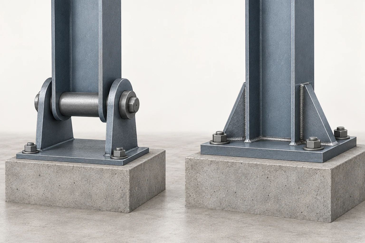
Reading the End-Restraint Context
Treat the two assemblies as qualitative boundary-condition cues only. The effective-length factor remains an idealized analysis assumption in the lesson, not a value encoded by the raster.
Interactive Exploration
Change column length, section dimensions, and idealized end condition. Observe how the weak-axis slenderness and Euler critical load change. Pay particular attention to the inverse-square effect of effective length.
Controls
Governing centroidal y axis.
r = √(I/A) about the weak axis.
K = 1.0
Ideal elastic bifurcation load, not a code design strength.
Euler stress is below the yield reference; real-column strength still requires imperfection, inelastic, local-buckling, and code checks.
Short, Intermediate, and Long Columns
Short columns are dominated by material strength. Very slender columns can be approximated by elastic Euler buckling. Between these limits, inelastic behavior, residual stress, imperfections, and material yielding reduce the validity of pure Euler theory. Practical structural design therefore uses code-based column-strength curves rather than applying Euler indiscriminately.
Column Proportion Contexts
The three connected specimens provide a qualitative visual of how member proportions change from stocky to slender; use the text and formulas for regime limits.

Reading the Proportion Comparison
No threshold or numerical slenderness is encoded. The practical classification depends on the governing material model and design standard.
Eccentricity and Imperfections
Real columns are not perfectly straight and loads are rarely perfectly concentric. Initial crookedness, residual stress, connection eccentricity, and frame sway introduce bending that grows with compression. The secant formula is a classical mechanics model for an ideal column with eccentric load, but modern building design should use the governing structural design standard.
Initial Column Imperfection
The paired columns contrast theoretical straightness with initial fabrication/geometric out-of-straightness before axial load is applied; the sweep is qualitative and unmeasured.
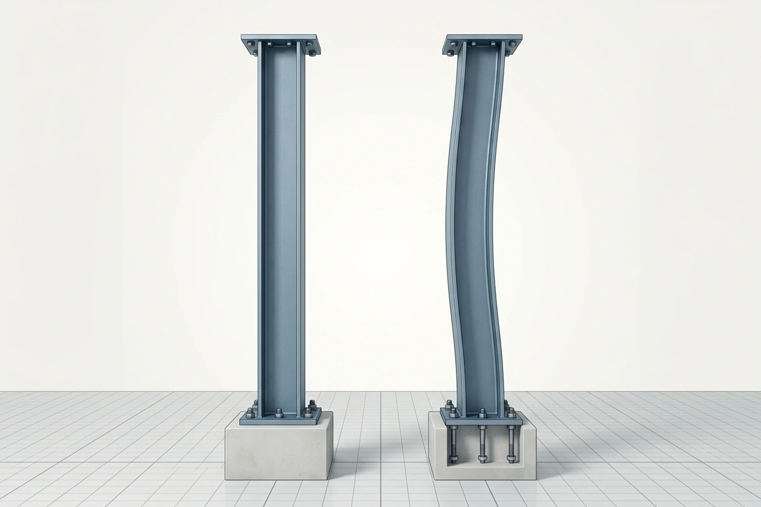
Reading the Imperfection Context
The gentle sweep is qualitative and intentionally unmeasured. It is not a tolerance, deflected shape, collapse state, or design conclusion.
Local versus Global Buckling
Global buckling deforms the member as a whole. Local buckling deforms individual thin plates or walls within the cross-section. A member can therefore be globally stocky while still containing a locally slender element; both behaviors must be considered when the section is formed from thin components.
Global and Local Buckling Modes
The left member bows as a whole while the right section keeps its overall axis and develops a localized plate wrinkle; exact slenderness and Euler behavior remain in the deterministic model.
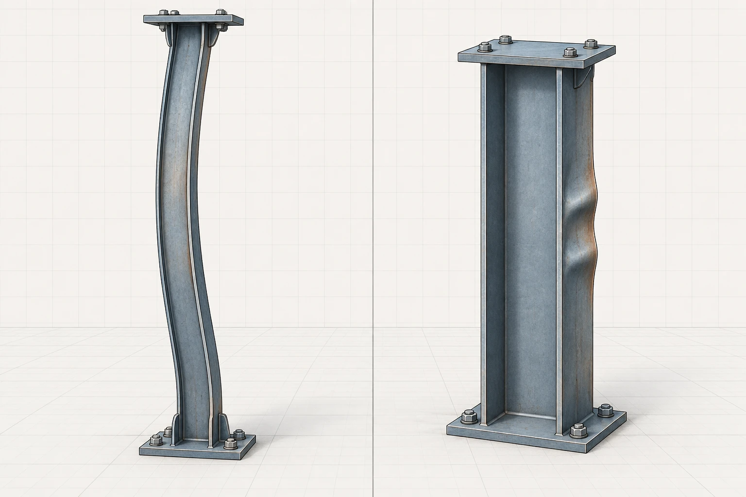
Reading the Buckling Comparison
Read the left and right states as different mode families: global buckling changes the geometry of the member over its length, while local buckling is confined to a thin flange, web, or wall element within the section. The exaggerated qualitative deformation is for mode recognition only; it does not identify a code limit, critical load, or tested failure.
Column Evaluation Workflow
This mechanics workflow separates geometry and stability checks from the later code-based member-design process.
Define column geometry, material, length, and restraints → Compute A, I, and r about each possible buckling axis; Compute A, I, and r about each possible buckling axis → Identify governing weak axis and effective length KL; Identify governing weak axis and effective length KL → Compute slenderness KL/r; Compute slenderness KL/r → Is ideal elastic Euler behavior a justified mechanics model?; Is ideal elastic Euler behavior a justified mechanics model? — Yes → Compute Euler P_cr and interpret elastic buckling; Is ideal elastic Euler behavior a justified mechanics model? — No → Recognize yielding, inelastic buckling, imperfections, or code-strength curve; Compute Euler P_cr and interpret elastic buckling → Are thin section elements susceptible to local buckling?; Recognize yielding, inelastic buckling, imperfections, or code-strength curve → Are thin section elements susceptible to local buckling?; Are thin section elements susceptible to local buckling? — Yes → Evaluate local slenderness using the governing design standard; Are thin section elements susceptible to local buckling? — No → Report governing stability mode and assumptions; Evaluate local slenderness using the governing design standard → Report governing stability mode and assumptions
- Define column geometry, material, length, and restraints: terminator
- Compute A, I, and r about each possible buckling axis: process
- Identify governing weak axis and effective length KL: process
- Compute slenderness KL/r: process
- Is ideal elastic Euler behavior a justified mechanics model?: decision
- Compute Euler P_cr and interpret elastic buckling: process
- Recognize yielding, inelastic buckling, imperfections, or code-strength curve: process
- Are thin section elements susceptible to local buckling?: decision
- Evaluate local slenderness using the governing design standard: process
- Report governing stability mode and assumptions: terminator
Euler Formula Is Not a Universal Design Equation
Euler's equation models an ideal, straight, prismatic, elastic column under concentric load with idealized end conditions. Do not use it as a complete real-building column design procedure without the checks and resistance factors required by the governing code.
- Column stability depends strongly on flexural stiffness, effective length, and weak-axis slenderness.
- Euler critical load varies with and inversely with .
- Real columns include imperfections, eccentricity, residual stress, and inelastic response.
- Practical design distinguishes material-dominated, inelastic, and elastic-buckling regimes.
- Local buckling and global buckling are distinct limit states.