Combined Stresses
Learning Objectives
- Superimpose compatible elastic stress components at a common point and on a common plane.
- Evaluate combined axial and bending stress produced by eccentric loading.
- Locate the neutral axis and identify when an eccentric compressive load causes tension.
- Apply the middle-third rule to rectangular sections carrying compression-only material systems.
- Combine beam normal and shear stresses before transforming the resulting stress state when necessary.
Combined Stress
Combined stress is the stress state produced when two or more loading actions contribute normal and/or shear stress at the same material point.
Superposition of Elastic Stresses
Under linear-elastic, small-deformation behavior, compatible stress components can be added algebraically. Add normal stresses to normal stresses and shear stresses to shear stresses using one coordinate and sign convention. Do not add scalar magnitudes that act on different planes without first resolving them to the same stress components.
Axial Plus Bending Stress
Normal stress at a point in a member subjected to axial force and bending moment.
Axial and Bending in One Member
The connected member-and-joint context makes axial and bending actions part of one physical system; use the adjacent formula for the local stress result.
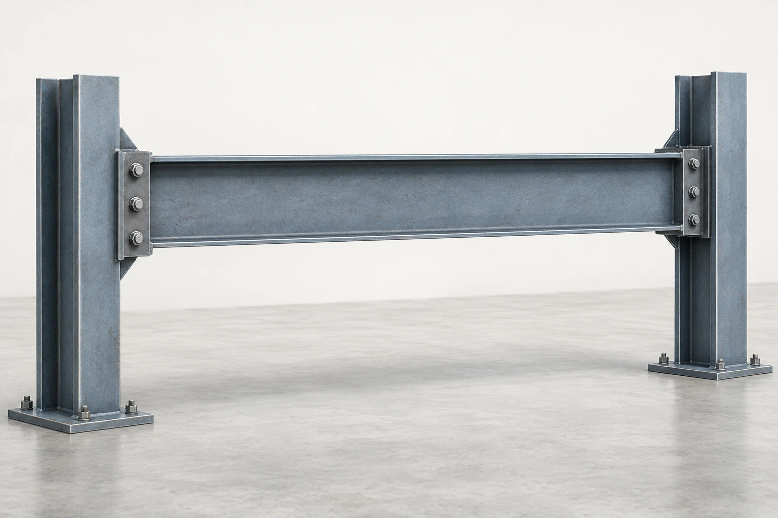
Reading the Member Context
The member is shown without arrows or stress shading on purpose. The raster identifies physical connectivity only; the adjacent formula and point-specific workflow define the combined stress state.
Eccentric Load
An eccentric axial load has a line of action offset from the centroidal axis, producing both a direct axial force and a bending moment.
Equivalent Eccentric Moment
Moment generated by an axial load with eccentricity e.
Offset Column Cap and Eccentricity
The offset bracket and supported girder seat provide a clear physical cue for an eccentric gravity load path; the adjacent equation supplies the exact moment relationship.
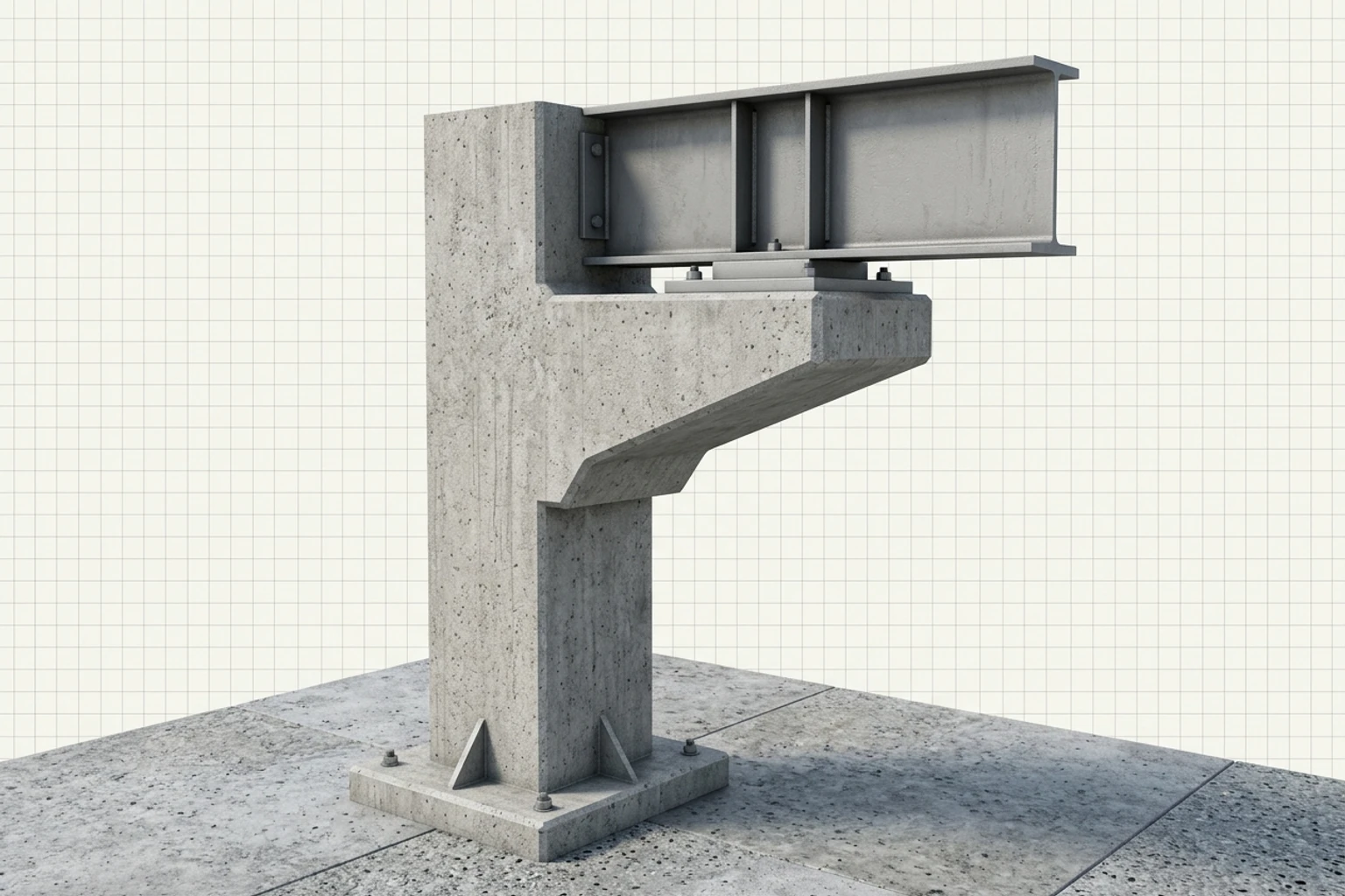
Reading the Offset Cap Context
The cap projection is a qualitative cue for offset alignment, not a prescribed proportion, load magnitude, or adequacy claim. Use the eccentric-load formula and interactive stress model for the mechanics.
Interactive Exploration
Vary compressive load and eccentricity in the combined-stress visualizer. Observe how the linear normal-stress distribution shifts and when one edge approaches zero or changes to tension.
Controls
P/A with compression negative.
M = Pe; sign follows e.
Top / bottom for the shown axis.
Both linear edge stresses remain compressive.
Kern
The kern is the region around a section centroid within which a compressive resultant must act to keep the entire cross-section in compression under linear elastic stress distribution.
Middle-Third Condition for a Rectangle
Compression-only eccentricity limit for bending about one centroidal axis of a rectangular section.
Middle-Third Rule
For a rectangular section loaded in compression about one centroidal axis, placing the resultant within the middle third keeps the calculated stress non-tensile across the full section. At , one edge reaches zero stress. Beyond that limit, the linear elastic full-contact model predicts tension at one edge and may no longer represent an unreinforced contact interface or masonry-like material accurately.
Eccentric Compression at a Wall Base
The offset wall and footing provide architectural context for eccentric compression and contact assumptions; use the adjacent simulation for the exact kern boundary and stress distribution.
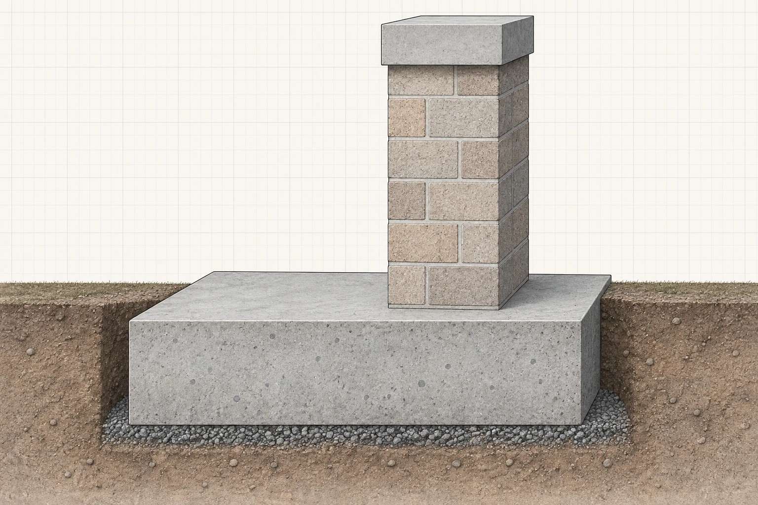
Reading the Wall-Base Context
The wall and footing are shown as an intact connected system with the load-bearing wall offset toward one side of the base. That spatial offset is a qualitative cue for eccentricity, not a prescribed proportion or a proof of adequacy. Use the middle-third condition, the interactive stress distribution, and a suitable contact model when full-area tension-free contact is no longer valid.
Interactive Exploration
Use the middle-third visualizer to move the compressive resultant across the section. Track the kern boundary and the transition from full compression to a stress distribution that includes tension.
Controls
For the displayed rectangular axis.
Outside-kern stresses are still shown as the linear full-area prediction, not a no-tension contact solution.
Compression
Compression
Combined Stress in Beams
A transversely loaded beam can have normal bending stress and transverse shear stress at the same point. Their individual maxima generally occur at different depths, so a critical combined state must be evaluated at the actual point of interest before principal stresses are calculated.
Beam-Column Joint Context
The cutaway locates a shared interface where normal and shear components may coexist; evaluate the local stress state at the actual point.
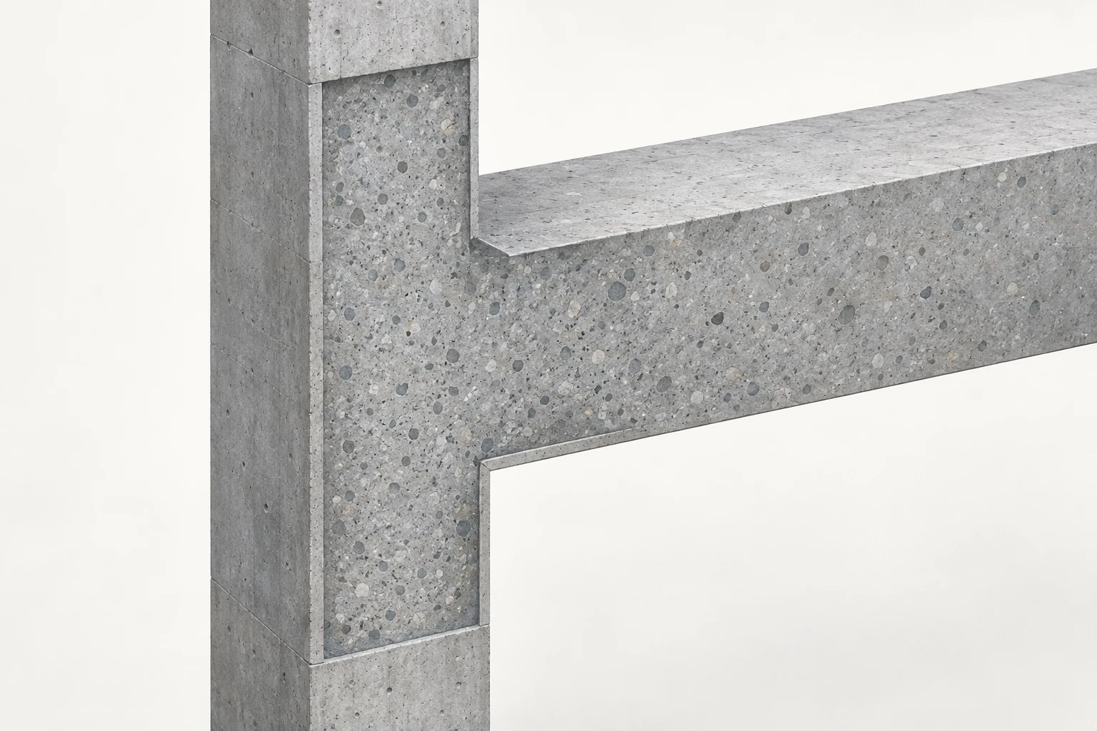
Reading the Joint Context
The image identifies the shared material region only. It does not provide joint detailing, force magnitudes, stress values, or a failure assessment.
Combined-Stress Workflow
Use a point-based workflow so stresses from different load effects are not incorrectly mixed between different section locations.
Choose the material point and coordinate system → Resolve axial force, moments, torque, and shear at the section; Resolve axial force, moments, torque, and shear at the section → Compute normal and shear stress components at that same point; Compute normal and shear stress components at that same point → Superimpose like components with consistent signs; Superimpose like components with consistent signs → Is compression eccentricity/contact behavior important?; Is compression eccentricity/contact behavior important? — Yes → Check neutral axis, kern, and possible loss of full compression; Is compression eccentricity/contact behavior important? — No → Are principal stresses or oriented-plane stresses required?; Check neutral axis, kern, and possible loss of full compression → Are principal stresses or oriented-plane stresses required?; Are principal stresses or oriented-plane stresses required? — Yes → Apply stress transformation or Mohr's Circle; Are principal stresses or oriented-plane stresses required? — No → Report governing point, stress state, and assumptions; Apply stress transformation or Mohr's Circle → Report governing point, stress state, and assumptions
- Choose the material point and coordinate system: terminator
- Resolve axial force, moments, torque, and shear at the section: process
- Compute normal and shear stress components at that same point: process
- Superimpose like components with consistent signs: process
- Is compression eccentricity/contact behavior important?: decision
- Check neutral axis, kern, and possible loss of full compression: process
- Are principal stresses or oriented-plane stresses required?: decision
- Apply stress transformation or Mohr's Circle: process
- Report governing point, stress state, and assumptions: terminator
Full-Contact Assumption
The middle-third result comes from a linear stress distribution over the full area. Once an interface cannot carry tension and contact lifts off, the effective compression zone changes and the simple full-area formula must be replaced by an appropriate contact model.
Rectangular Footing Contact Context
The cutaway emphasizes the connected footing, bearing layer, and ground interface; use the middle-third and contact models for the actual contact region.
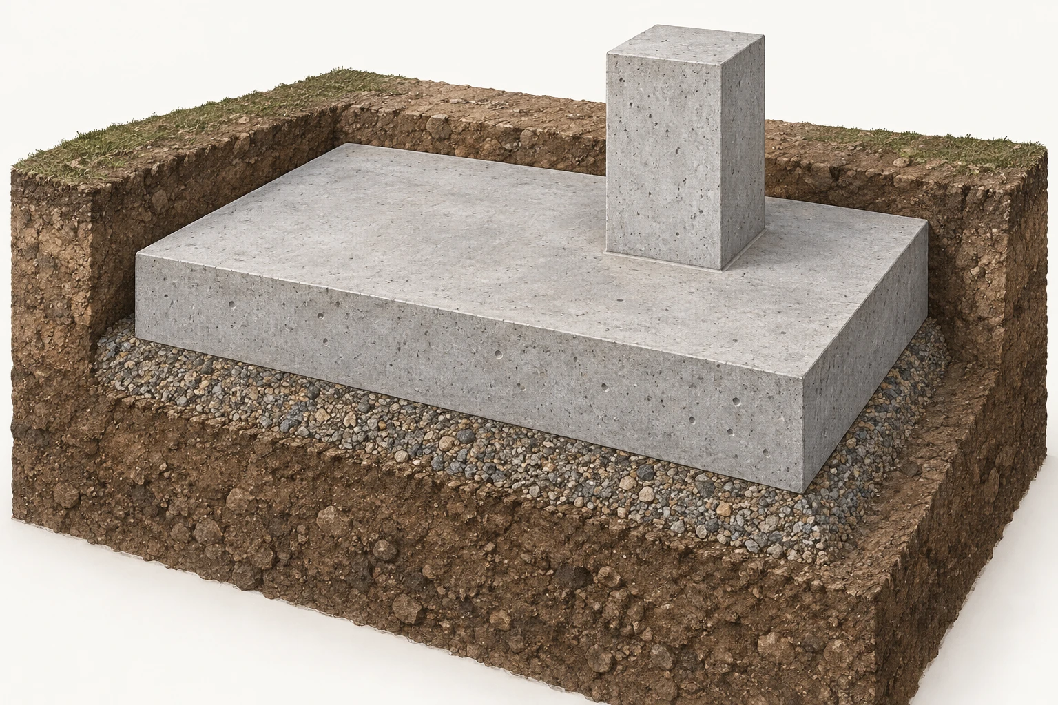
Reading the Footing Interface
The visible underside is a physical interface, not a pressure diagram. No contact width, pressure distribution, code limit, or adequacy conclusion can be inferred from the raster.
- Combine stress components only at the same material point and in the same coordinate system.
- Eccentric axial load is equivalent to a centroidal axial load plus the moment .
- For a rectangular compression section, the middle-third rule identifies the full-compression kern limit.
- Maximum bending stress and maximum transverse shear stress usually occur at different depths.
- Use stress transformation only after the local combined stress components have been established.