Principal Stresses and Mohr's Circle
Learning Objectives
- Describe a plane-stress state using normal and shear stress components with a consistent sign convention.
- Transform stresses to an arbitrarily oriented plane.
- Determine principal stresses, maximum in-plane shear stress, and their orientations.
- Construct and interpret Mohr's Circle as a graphical representation of the same transformation equations.
- Distinguish in-plane maximum shear from absolute maximum shear when a third principal stress is relevant.
Plane Stress
Plane stress is a two-dimensional stress state in which the out-of-plane stress components are negligible relative to the in-plane components.
Thin Plate Plane Context
The plate's small through-thickness edge and broad connected surface give physical context for idealizing a thin member as a material plane; exact out-of-plane assumptions belong to the definition and equations.
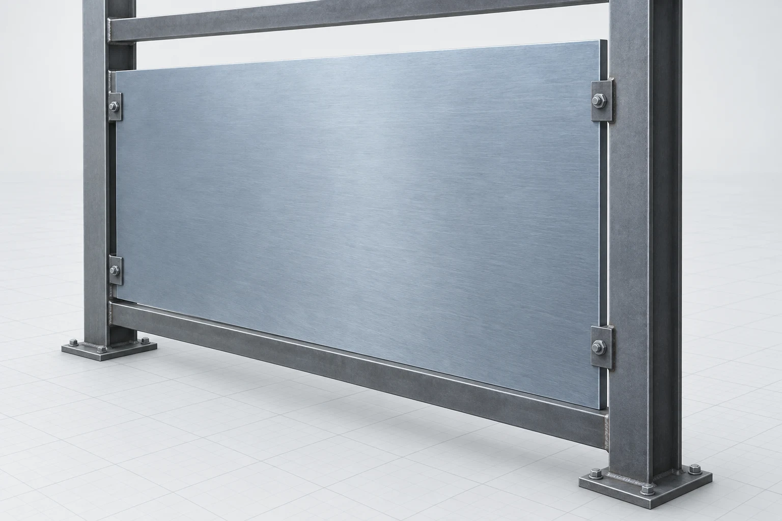
Reading the Thin Plate Context
The broad plate surface is a qualitative material-plane cue, not a plane-stress label or a measured statement about an out-of-plane component. Apply the idealization only with the assumptions stated in the lesson.
Plane-Stress Transformation
Normal and shear stresses on a plane rotated by angle theta from the x face.
Why Orientation Matters
The stress state at a point is fixed, but its normal and shear components depend on the orientation of the plane used to describe it. Stress transformation resolves the same physical state onto a rotated set of faces; it does not create additional load.
Alternate Material-Plane Context
The connected steel cutaway gives a physical context for asking how the same point can be described on different plane orientations; exact stress components, angle relations, and Mohr-circle geometry remain in the equations and simulator.
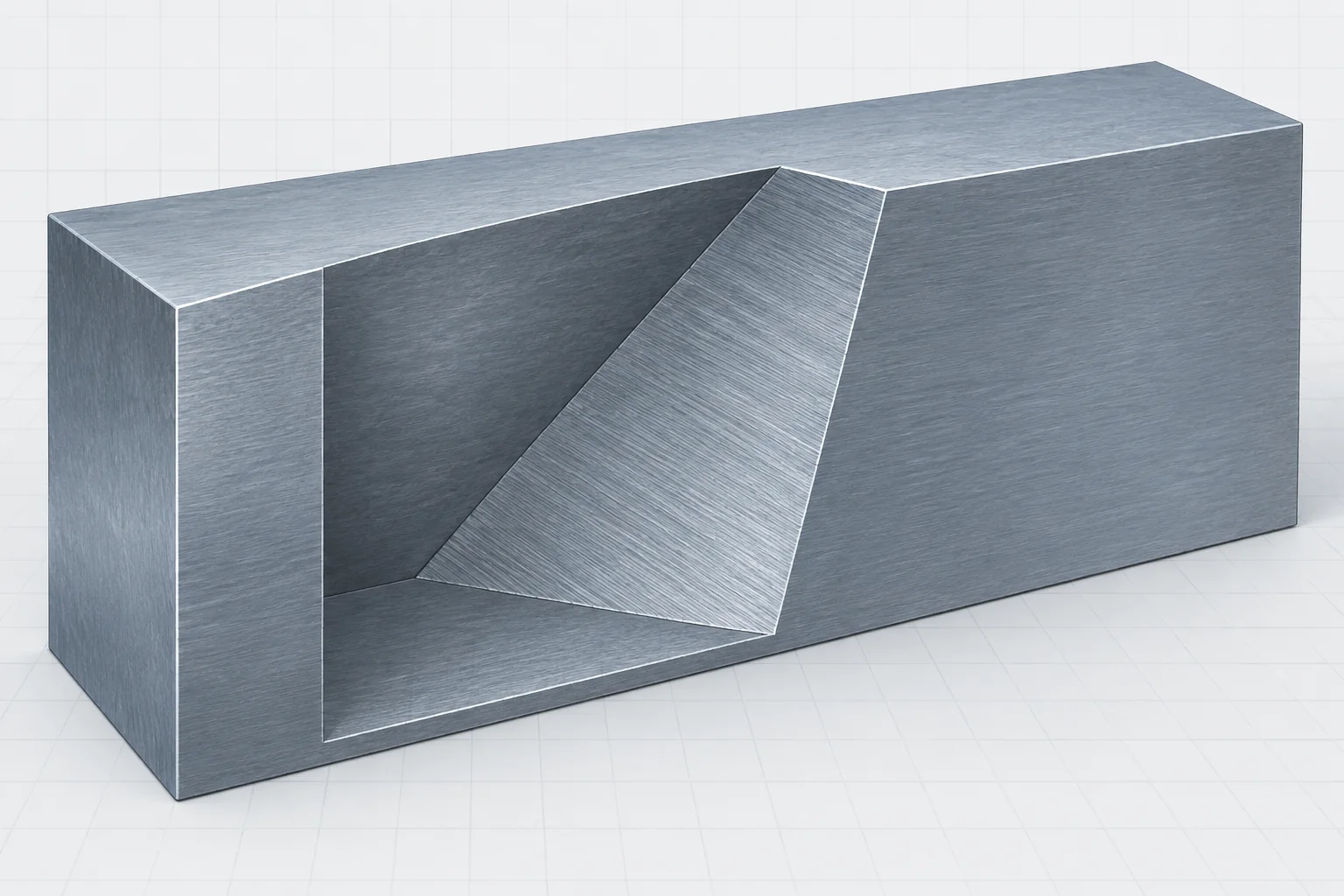
Reading the Rotated-Plane Context
Treat the oblique cut as a qualitative view of a different plane through the same material—not as a drawn principal plane or a scaled stress diagram. The exact transformed normal and shear components, angle, and sign convention come from the formulas and simulation.
Principal Stress
Principal stresses are the normal stresses acting on planes where the corresponding shear stress is zero.
Biaxial Material Region
The orthogonal frame and intact plate region provide physical context for two normal directions acting within the same material plane; use the formulas and simulator for components and principal values.
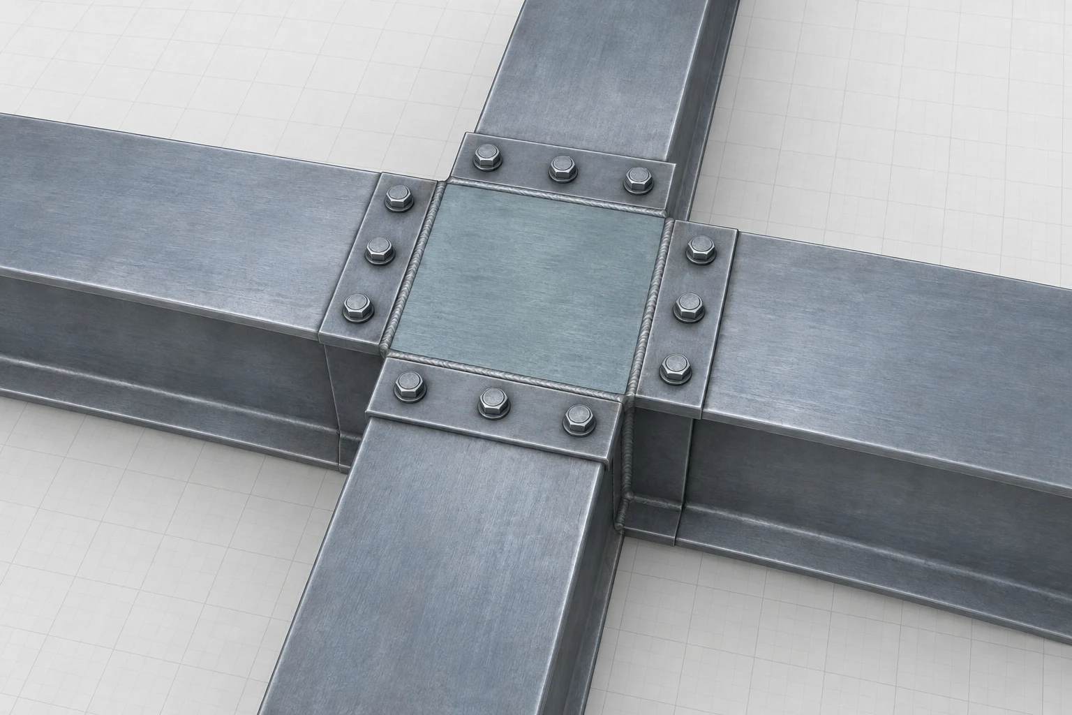
Reading the Biaxial Region
The connected plate region makes two in-plane directions visible through the surrounding geometry, but it does not encode stress signs, magnitudes, or principal values. Those quantities come from the stated stress state and transformation model.
Principal Stresses
Maximum and minimum in-plane normal stresses for a plane-stress state.
Maximum In-Plane Shear Stress
Radius of Mohr's Circle and the maximum in-plane shear stress magnitude.
Maximum-Shear Plane Context
The alternate diagonal plane changes the viewing cut through one coherent element, providing context for orientation-dependent shear; no failure or shear magnitude is implied.
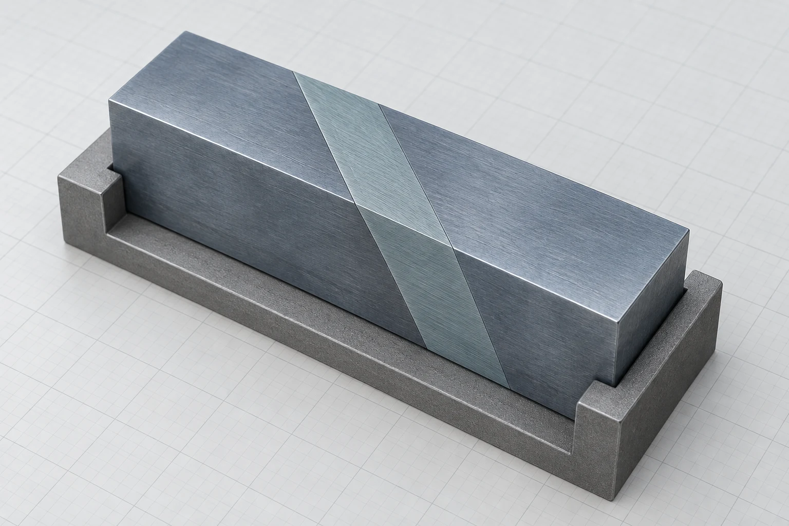
Reading the Diagonal Plane
Treat the clean diagonal cut as an idealized observation plane through the same element, not as a crack, failure surface, or measured maximum-shear plane. Exact orientation and shear magnitude remain in the equations and simulator.
Mohr's Circle
Mohr's Circle is a graphical construction in normal-stress versus shear-stress coordinates that represents all transformed plane-stress states at a point.
Mohr's Circle Geometry
The circle center is on the normal-stress axis. Its radius is the maximum in-plane shear stress. The horizontal intercepts are and . A physical rotation of corresponds to a rotation of around Mohr's Circle, with the direction governed by the adopted shear-sign convention.
Interactive Exploration
Change , , and . Track the circle center, radius, principal-stress intercepts, and maximum-shear points. Use the visual to verify—not replace—the transformation equations and sign convention.
Controls
(σx + σy)/2
Maximum in-plane shear magnitude.
σ1 and σ2 are the horizontal circle intercepts.
One solution from ½ atan2(2τxy, σx−σy); the other is 90° away.
Stress Transformation Workflow
The workflow below keeps the algebraic and graphical methods synchronized and provides explicit checkpoints for sign and orientation errors.
Define sigma_x, sigma_y, tau_xy and sign convention → Compute center C and radius R; Compute center C and radius R → Compute sigma_1 = C + R and sigma_2 = C - R; Compute sigma_1 = C + R and sigma_2 = C - R → Set maximum in-plane shear magnitude equal to R; Set maximum in-plane shear magnitude equal to R → Determine principal/shear-plane orientation using 2-theta relation; Determine principal/shear-plane orientation using 2-theta relation → Do transformed stresses and circle points satisfy the chosen convention?; Do transformed stresses and circle points satisfy the chosen convention? — Yes → Report stresses, orientations, and assumptions; Do transformed stresses and circle points satisfy the chosen convention? — No → Correct sign convention or angle direction; Correct sign convention or angle direction → Compute center C and radius R
- Define sigma_x, sigma_y, tau_xy and sign convention: terminator
- Compute center C and radius R: process
- Compute sigma_1 = C + R and sigma_2 = C - R: process
- Set maximum in-plane shear magnitude equal to R: process
- Determine principal/shear-plane orientation using 2-theta relation: process
- Do transformed stresses and circle points satisfy the chosen convention?: decision
- Correct sign convention or angle direction: process
- Report stresses, orientations, and assumptions: terminator
Absolute Maximum Shear
For a three-dimensional stress state, compare all three principal stresses. The absolute maximum shear stress is half the largest separation between any pair of principal stresses. Under plane stress, the third principal stress is commonly , which may make the absolute maximum shear different from the in-plane maximum.
Three-Dimensional Stress-State Context
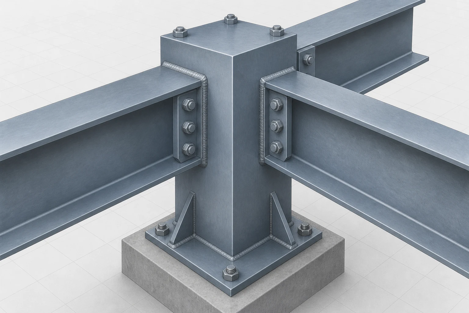
A finite-thickness block joined across multiple faces makes out-of-plane interaction physically visible; use the principal-stress discussion for deciding when a third component matters.
Reading the Thick Solid Context
The visible thickness distinguishes this solid context from a thin plate, but the raster does not encode coordinate axes, principal labels, a tensor, or numerical values. Those remain in the lesson's definitions, formulas, and interactive model.
Mohr's Circle Sign Convention
Textbooks and software do not all plot positive shear in the same vertical direction. State the convention and use it consistently when mapping between physical rotation and circle rotation. Principal-stress magnitudes are convention-independent; plotted rotation direction is not.
- Stress components change with plane orientation even though the physical stress state does not.
- Principal planes carry zero shear stress, and their normal stresses are the extrema and .
- The Mohr-circle radius equals the maximum in-plane shear stress magnitude.
- Physical angle and Mohr-circle angle are related by a factor of two.
- For absolute maximum shear, include the third principal stress when it is relevant.